How to Determine Which Laser Scanning Registration Method is Right for You


Error Propagation
Now that we have looked at different ways to prepare registration, figured out when best to use targets compared to cloud-to-cloud, and what survey control is, we need to talk about the errors involved in registration. This involves figuring out how to minimize any mistakes associated within registration – and yes, there will be some!
Error propagation is the accumulation of errors in a scanning project. There are two main things that affect this: scanner accuracy and registration errors. Let’s first take a look at scanner accuracy. All scanners have some error to them ¬— they are not perfect — and these errors will propagate if you are not careful.
On most tech sheets, you will see a line that says, “3D point accuracy = +/- 3.5mm @ 25 m.” What does this mean? It means three things, or an accumulation of three different types of errors. A range error, or distance error, is number one. Doucet explains, “The scanner shoots a laser, it has to return back, [and] it measures the distance. There’s error in that distance. It’s called ranging error.” The second one is horizontal angle error, where the scanner is rotating horizontally and experiences an error in that angle. Lastly, there’s vertical angle error.
Let’s say, for example, that you’re shooting an object that’s 25 meters away. With the information supplied to you from that tech sheet, you’re going to get an uncertainty of +/- 1 millimeter error from that distance. For a horizontal angle, it is a similar concept. Looking at a building that is once again 25 meters away, if you have a horizontal angle of +/- 19” (arc seconds), that is going to equate into an uncertainty of +/- 2.3 millimeters. And the same goes for vertical angle as well.
Another subsequent error is how well the scanner levels itself, otherwise known as the leveling error. If the scanner can only level itself to +/- 19” (arc seconds), that means 25 meters away, you are going to be out an uncertainty of +/-2.3 mm from your horizontal plane. Some scanners have a survey-grade dual-axis compensator that can be set up and leveled over a known point. Using a laser scanner with a dual-axis compensator also allows you to obtain real-time coordinates in the field without having to post-process the scan data.
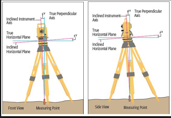
Credit: FARO webinar
Another subsequent error of registration is how well the scanner levels itself, otherwise known as the leveling error.
If you want to minimize that leveling error and create dual axis compensator optimization, you need to do your due diligence and treat the scanner as if it were a total station needing the proper accessories. These include a quick release and survey adaptor, a survey tribrach (optical or laser), and survey tripod. For the best results, make sure to use a high precision survey tribrach (8’ vial).
Registration Errors and Loops
Next, let’s talk about registration errors. These errors occur when we do not close our loops. What does that mean? Let’s take a nice, long street as our example. Youare scanning the road, going down the street, until you are ending on the last scan. Let’s say you have four different positions. This is what is called a linear open loop. With an open loop, we keep scanning and the error just keeps continuing. We don’t know where the last scan is placed, if it is in the right location or not, compared to the first scan, so the errors just keep increasing in this type of scanning scenario.
For a closed loop example, let’s envision a mechanical room. We will start scanning in the top left corner, go around the mechanical room, moving the scanner nine different times, and then we close our last scan in the proximity of the first scan. In the closed loop scenario, the errors are somewhat evenly distributed. The first scan and the last connect with each other, which means the error propagation is evenly distributed throughout the entire project.
With our street example, one scan only sees the scan ahead of it and behind it, which is prone to a lot of errors. With our mechanical room example, one scan can see almost every other scan. This tightens up your entire scanning network and will reduce the error propagation in itself.
So, our next question is, how do we control these open loop scans? According to Doucet, we control it with survey control. “That’s what survey control is,” he says. “It controls the errors in your project and controls the coordinate system of your entire project as well.”
Going back to our street, if we insert control points, or spheres, throughout our scanning, those control points are tied to a survey control grid, which has coordinates down to a millimeter or so of accuracy. If you place those markers throughout the project, then you can minimize error propagation using survey control in an open loop scan. In this scenario, using the spheres, the errors don’t accumulate and get evenly distributed, resulting in a nice, even, tight registration.
What about when it comes to scanning multiple levels of a building? Different floors might present a challenge when it comes to piling on errors. Once again, the answer is survey control. You input control points throughout the project, introducing survey control on each level of the building. Level one becomes cluster one, and so on and so forth. Each floor is independent of any other clusters in the building. This means that you can register cluster two without having any overlap from cluster one or cluster three. All clusters will end up in the right place, and the scans error propagation will even out into a straight line.
Open Loop Problems
Though open loop systems can be fixed with survey control, they can also be a problem in some environments. Let’s say you’re scanning a building that’s mostly concrete and around 200 feet. Will error propagation be a problem here? What about with a 3,000-foot tunnel?
Error propagation won’t be a problem with the building, as it is negligible. But with the tunnel, it will be an issue if survey control is not introduced.
For the building that is under construction, let’s say we take 25 to 30 scans of the building using the cloud-to-cloud registration method. The scans come back, they look good, the recording is very tight, and then we move the cluster of scans all to survey control using a few checkerboards. Those scans are very good as well. Basically, what we’ve done is aligned the scans to each other using cloud-to-cloud, moved them all to survey control, and then we’re looking at the errors of the control compared to the checkerboards. Turns out, for this example, there is no real pattern between the two, which means the errors are not getting worse as we are moving down the building. So error propagation is not something that will need to be worried about with a building such as this.

Credit: FARO webinar
An example of when an open loop is a problem when it comes to registration and error propagation.
Going back to the 3,000-foot tunnel, we need to examine the error propagation of this open loop project. With a tunnel of this length, there’s definitely going to be a problem, whether you’re using cloud-to-cloud or target-based registration. Those issues are going to arise if you don’t bring in survey control. So, let’s say you do a target-based registration using matched spheres to 5/100-foot at control points A and B at the beginning of the tunnel (see Figure 7 for reference). These control points are survey control, and then we see where control point C falls at the other end of the tunnel. We then notice it is close to a foot out from Sphere C. What do you do now?
In short, we don’t have control at the end of the tunnel; you have an open loop. In order to solve this problem, you have to introduce control to make sure your scans don’t veer off in the wrong direction. That means target-based registration with survey control using high weights on survey control to realign the scans. Another reason for such error within the tunnel is that the tunnel itself is maybe 6-feet wide, so the spheres are all tied to each other, resulting in bad geometry of your targets because theyare so tight to each other.
High Detail Target Scanning
High detail target scanning allows for large-field scanning by targeting certain areas for high-resolution scanning while leaving other areas low-resolution. This makes it possible to scan a big, expanded area without moving the scanner every 20 feet or without using solely high-resolution scans, which is inefficient. High detail target scanning is beneficial for a number of reasons, but primarily so you can stretch out the scan positions as much as possible to make the entire process more effective.
For example, let’s say you’re doing a long-range project and you’re using spheres in order to accomplish target-based registration. You could be 200-feet away from one scan to the next, which is a multitude of data for the deliverable. But the problem is the spheres are going to be a little too far away from the scanner. If the distance is too far, you’re unable to get enough points on the sphere, meaning you can’t model it, and are unable to capture the center of it in order to run target-based registration. To capture enough scan points on the spheres at those distances, high resolution scans will need to be required.
What about a dynamic environment such as a bridge with nearby water, homogenous features, and moving traffic above and below the bridge? With such an active setting, target placement can be a bit more difficult. The key is, you have to make sure your spheres or your checkerboards are on solid ground. “That’s the trick,” Doucet says. The same goes for if you’re using a total station, as you can’t set up your controls on moving ground. In this situation, put your spheres a little farther out from the site and use high detail target scanning to really scan and focus on the far-away spheres.
High detail target scanning allows the scanning of those spheres in high resolution, which creates plenty of points on the spheres. It’s important to note that only the targets are scanned at high resolutions. Your normal scans will remain in normal resolution that is commonly used for outdoor settings, and field time is not increased in relevant scan projects. But now you might be asking, why not just scan everything in high resolution? Aren’t they reasonable? The answer is, high resolution scans are very large and have the possibility of creating bottlenecks in processing and in data extraction/modeling. In a high resolution scan, there are approximately 12 million points in one scan. There are around 3 million points in the same scan at medium resolution. That also equates into 1 gigabyte versus 160 kilobytes of storage capacity.
Let’s do a real world example. Let’s say you’re scanning a busy construction site. Where would you place permanent targets/survey control points? For a busy site such as this, you would want to put them outside of any high traffic work areas on stable ground conditions. Another option is putting checkerboards on an adjacent building because there won’t be any subsequent movement. Then, use high detail target scanning from a far distance and regular scans in the high traffic areas.
