Embracing the Timber Age


Fire Protection
While fire protection is not the focus of this course, the CLT assembly’s combustibility may need to be considered to meet local building- and fire-code requirements. Often, the CLT itself will meet the required fire rating for the assembly. However, in some cases, an additional noncombustible thermal barrier may be required, such as exterior gypsum sheathing. In these instances, some products can be applied directly to the gypsum sheathing, similar to a typical installation over a framed wall.
In taller CLT buildings, the combustibility of the WRB membrane may also need to be considered. For construction exceeding 40 feet, Section 1402.5 of the 2018 IBC requires that CLT wall assemblies with a combustible WRB membrane are tested following NFPA 285 procedures to demonstrate conformance with fire performance requirements. The code currently does list exceptions for the testing requirements where the assembly is deemed to comply if the WRB is the only combustible component and has: 1) a peak heat release rate (HRR) of less than 150 kW/ m2, a total heat release of less than 20 MJ/m2, and an effective heat of combustion of less than 18 MJ/kg when tested per ASTM E1354; and 2) a flame-spread index of 25 or less and a smoke-developed index of 450 or less when tested per ASTM E84.9.
It should be noted that CLT construction practices are still relatively new in North America, and codes are continuously being updated to accommodate more prescriptive paths to CLT assembly fire compliance. This course recommends that project-specific fire-protection requirements are confirmed with the local jurisdiction having authority.
Termite and Pest Protection
In areas where termites and other wood-burrowing pests are prevalent, local codes may require protective measures for insect damage at CLT. These measures can be especially important at exposed areas of CLT and at grade where CLT is in contact with the foundation. To protect against termites and other pests, pest-sensitive CLT areas can be preservative treated and termite soil barriers introduced into the foundation design, such as termiticide soil treatments and separation membranes between the foundation and CLT. Regardless of the local termite risk, pest-control measures, such as insect screens at cladding openings and separation membranes at footings, are best practices in all regions.
CLT Wall Design and Best Practices
Now that a number of important building enclosure design principles have been established, they can be applied to CLT wall and roof assemblies.
The two options available for CLT wall assemblies in cold climates (i.e., Climate Zones 4 through 8) are closed-joint cladding and open-joint cladding (see Details 1 and 2). Both assemblies rely on a rainscreen strategy for managing rainwater, and in some North American regions, this is known as a drained and ventilated strategy, writes John Straube, Ph.D., principal, RDH Building Science, Toronto, in his Rain Control in Buildings white paper.
In a CLT structure, exterior cladding surfaces, flashings, and enclosure projections shed and deflect most of the incident rainwater. Incidental water that bypasses the exterior cladding of a rainscreen system is then managed by the following means:
- The weather-resistive barrier that serves as a drainage plane. Either a self-adhered WRB/AB or a black, UV-stable WRB/AB may serve as the membrane in the assemblies shown in Details 1 and 2.
- A clear air gap to allow water to drain. This air gap is also ideally designed to allow ventilation to improve the drying potential for moisture contained in the drainage cavity and at the backside of the cladding material.
- Deflection mechanisms such as flashings to drain water back to the exterior.
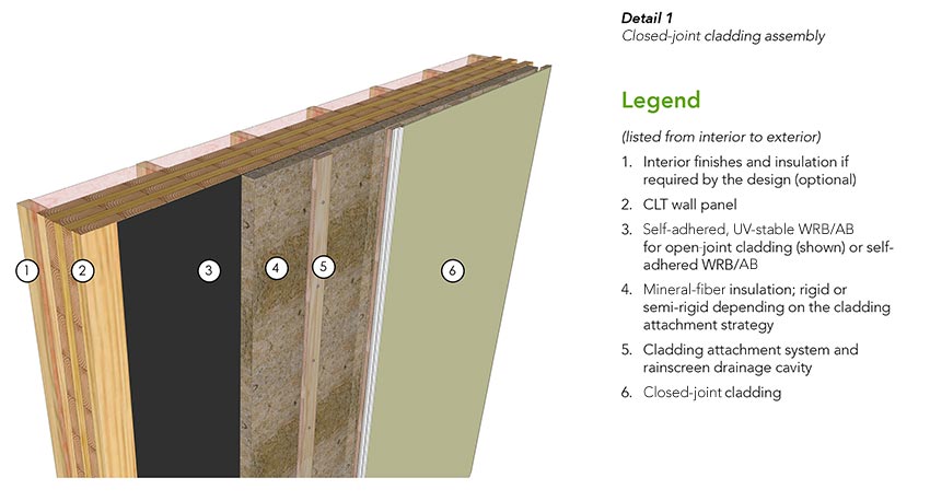
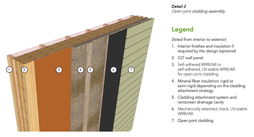
In these assemblies, the WRB also functions as the AB. The wall assemblies are exterior insulated with vapor-permeable mineral-fiber insulation to permit outward drying. If a vapor-impermeable insulation type is used, the assembly should be carefully evaluated by a design professional to ensure the wall design does not increase risk for moisture accumulation within the wall assembly.
In some cases, batt insulation may be added inboard of the CLT panel if required for sound attenuation or to improve the thermal performance of the assembly. However, the amount of interior insulation must be carefully balanced with the exterior insulation. Again, the interior insulated assemblies should be evaluated by a design professional to minimize the risk that condensation may form within the assembly.
For the open-joint cladding system shown in Detail 2, a sheet of black, mechanically attached WRB/AB is provided directly behind the cladding material and attached to the vertical furring. This serves to protect the insulation, the WRB, and other UV-sensitive components from UV rays. It also functions as an additional drainage plane immediately behind the cladding to shed the increased water load resulting from the open cladding joints.
Cladding Attachment Considerations
Cladding attachment penetrations through the WRB/AB membrane require careful consideration. As discussed earlier, cladding attachments can impact the thermal performance of the assembly as well as disrupt the WRB/AB if not carefully designed.
The four most common cladding attachment systems are a long screw with wood furring strips, clip and rail system, vertical girt, and horizontal girt.
Long screw with wood furring strips: Long screws through the insulation can be a cost-effective and thermally efficient option for the attachment of light- to medium-weight claddings. With this system, the cladding is attached to treated vertical wood furring strips placed against the face of a rigid mineral-fiber insulation. The furring strips are fastened back through rigid mineral-fiber insulation to the CLT panel. Additional detailing is typically not required where the fastener penetrates the WRB/AB.
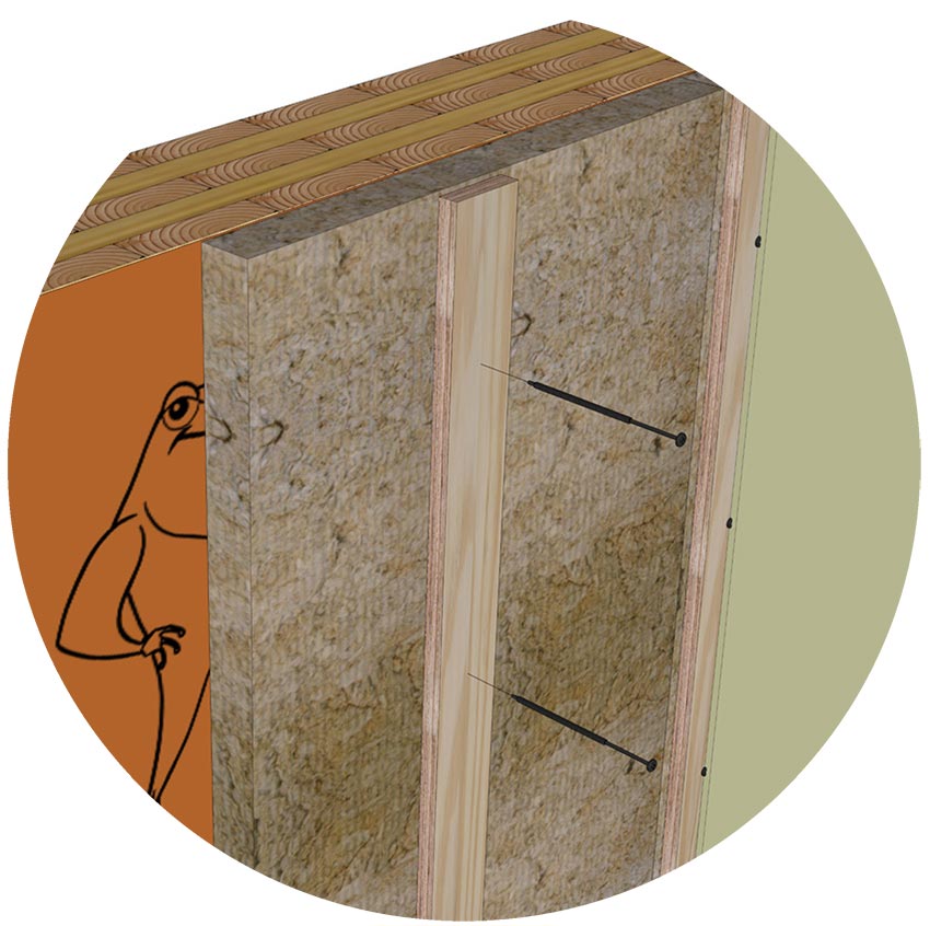
Figure 3-1
Long screw with wood furring strips
Clip and rail systems: The cladding is attached to vertical or horizontal metal girts. The girts, or rails, are attached to intermittent clips that bridge the insulation and are attached to the CLT structure. The insulation may be rigid or semi-rigid mineral fiber. However, semi-rigid insulation is typically easier to fit around the clips. Additional detailing is typically not required at clip-fastener penetrations through the WRB/AB or when the clips are installed tight to the membrane. However, when clips are not installed snug to the wall, the gap created behind the clip can trap water, increasing the risk for water ingress at fastener penetrations. A neoprene shim or silicone sealant are used at fastener locations to seal around the fastener in these scenarios.
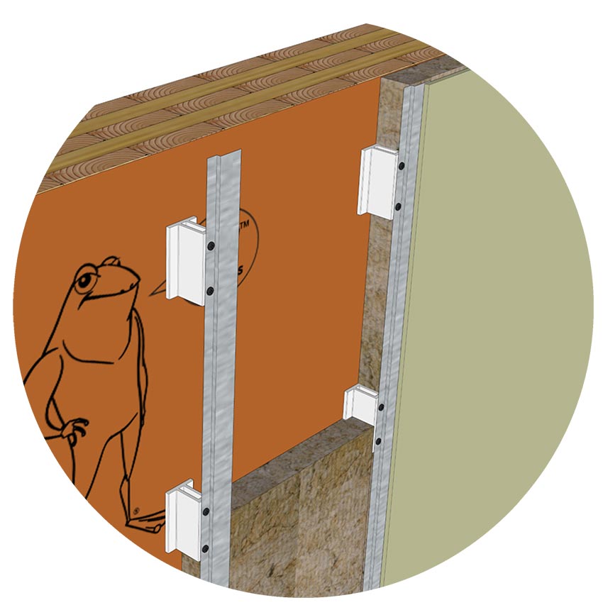
Figure 3-2
Clip and rail systems
Vertical girt: Vertically oriented girts are a common form of cladding attachment with rigid or semi-rigid mineral-fiber insulation types. Continuous metal girts significantly degrade the performance of exterior insulation, but more thermally efficient girts made of less thermally conductive materials are available. Similar to the clip and rail system, girt-fastener penetrations through a WRB/AB do not typically require additional detailing if the girt is installed tight to the wall. Where girts are not tight, a neoprene shim or silicone sealant is used at fastener locations to improve the seal at fastener penetrations.
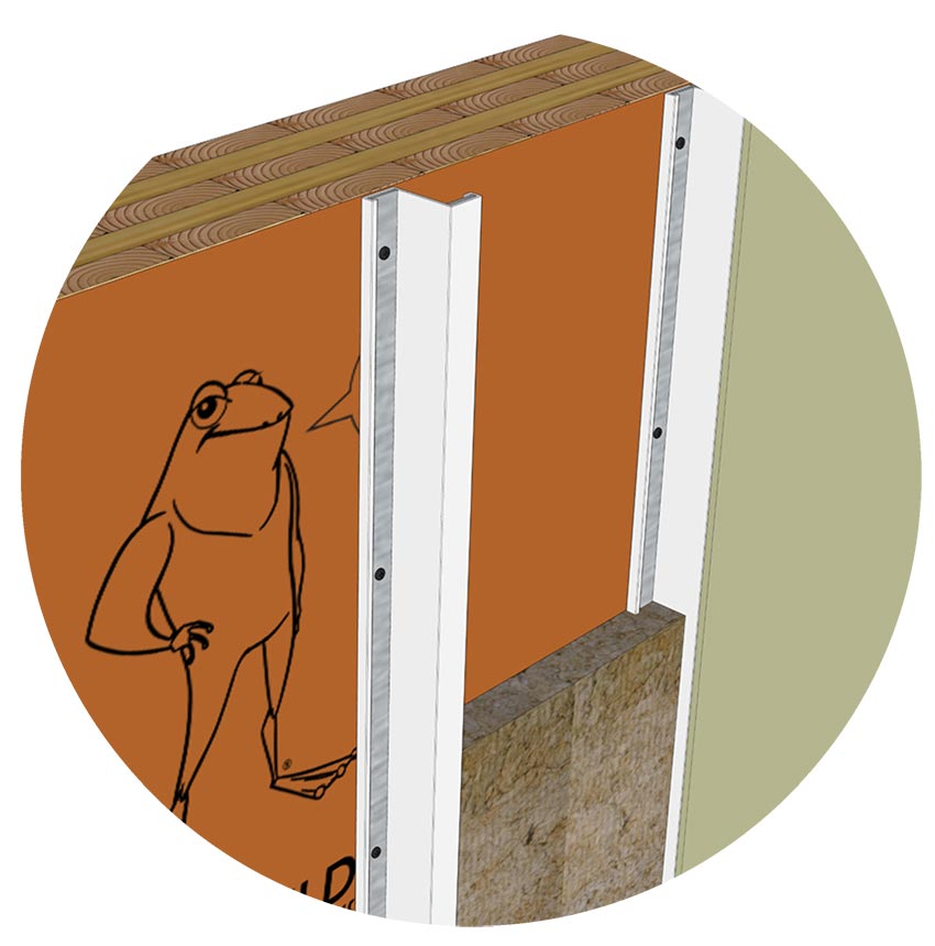
Figure 3-3
Vertical girt
Horizontal girt: Continuous horizontal girts can significantly degrade the performance of exterior insulation unless non-metal girts are used. Horizontal girts without flutes or perforations installed tight to the WRB may block the drainage path at the WRB plane. Some systems require that the horizontal girts are shimmed with a barrier to provide a continuous drainage plane and to seal around girt fastener penetrations through the membrane. Rigid or semi-rigid mineral-fiber insulation types can be used with this attachment approach.
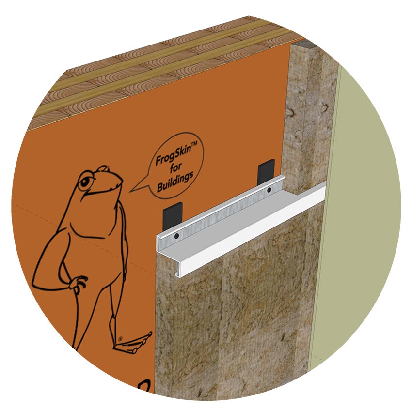
Figure 3-4
Horizontal girt
