Opportunities For Wood in Low-Rise Commercial Buildings


Wall Bracing
While prescriptive braced wall panels are an option for wall heights up to 12 feet (covered in IBC Chapter 23 and the International Residential Code), this section focuses on the more commonly used engineered wall systems for lateral force resistance, including:
- Engineered wood structural panel-sheathed shear walls
- Prefabricated shear wall products
Shear walls have four main components or component systems—wall framing, sheathing, base anchorage, and end posts—which function both individually and together as a unit. Wall framing includes studs, blocking between studs, and sole and top plates. Sheathing includes wood structural panels as well as their attachment to the wall framing. Base anchorage includes any attachment method used to anchor the base of the shear wall to the wall/floor/foundation below to resist unit shear and unit uplift (if applicable). This could be done with anchor bolts into the foundation, or nails, wood screws, or lag screws into a wood-frame wall or floor below. End posts, also known as boundary members, are located at each end of the shear wall and resist the overturning tension and compression forces. Load path for tension forces is developed through the use of hold-down systems, which tie the end post to the foundation or framing below.
Requirements for nailed shear walls, including in-plane unit shear capacities and construction details, can be found in the SDPWS. The following three shear wall design approaches are recognized in the SDPWS and widely used:
- The segmented shear wall approach uses full-height shear wall segments with no openings, each with full end restraint against overturning.
- The force transfer around openings (FTAO) approach utilizes strapping to transfer forces around openings.
- The perforated shear wall method provides a way to account for the strength and stiffness of shear walls with openings, while providing an alternative to the strapping around openings required by the FTAO method.
For large open-front buildings, where the maximum height-to-width aspect ratio of wood structural panel-sheathed shear walls of 3:5 to 1 may not be available, a variety of prefabricated narrow shear wall systems are available. These panels can be wood-frame or a combination of wood and steel-frame. They generally utilize the concept of segmented shear wall design, with the exception that some are intended to be used in tandem to create a portal frame system. Designers considering the use of these systems should be aware of the following:
- Because they’re quite narrow, the magnitude of hold-down forces at the ends of the wall can be significant, making the anchor bolt detailing and construction critical.
- Some of these systems have relatively large in-plane deflections at their full load capacity, making it important to account for the effect of large deflections on performance of wall finishes such as gypsum wallboard.
- While there are some similarities among them, they’re proprietary systems and a designer can be locked into a specific design without any flexibility for field modification.
Deflection compatibility with other walls is another design consideration. The common assumption of distribution of load (on a pounds per lineal foot of wall basis) does not apply when mixing prefabricated shear walls with wood structural panel-sheathed shear walls. Guidance on distribution of load based on deflection compatibility can be found in the SDPWS and the technical support documents provided by manufacturers.
These systems also result in very large uplift forces on the hold downs to the point that post-installed concrete anchorage systems typically don’t work. Rather, cast-in-place concrete anchorage (with careful coordination of the framing and anchorage installation) is often required.
Another option that may be available is to design a building with no shear walls on one side. In the 2008 SDPWS (and earlier), there were two design approaches that allowed this—cantilever diaphragms and open-front structures—each with its own (though similar) requirements. In the 2015 SDPWS, these concepts have been combined, as shown in Figure 4. In the 2015 SDPWS, a cantilever diaphragm is a horizontal floor or roof system that distributes horizontal loads to shear walls and is not laterally supported at one edge. An open-front structure is a structure with a cantilever diaphragm.
NEW HEIGHTS PHYSICAL THERAPY
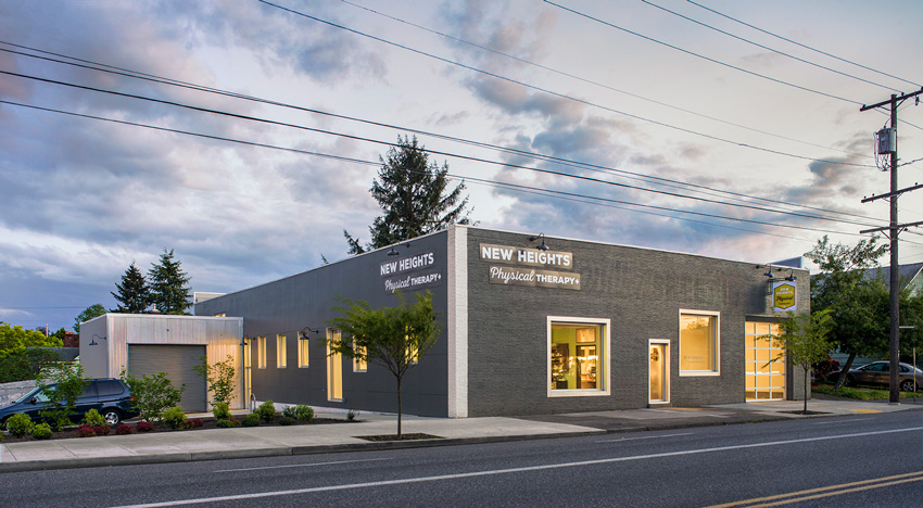
Photo: Eckert and Eckert Photography
Location: Portland, Oregon
Architect: Constructive Form Architecture and Design LLC
Engineer: James G Pierson Inc.
This 7,000-square-foot office recently underwent a major adaptation from a metal shop to an Assembly/Business occupancy. The roof is a mix of dimension lumber, glulam, LVL, LSL, and PSL. Flooring is comprised of I-joists, glulam, LVL, LSL, and PSL. Walls are dimension lumber studs.
Figure 4: Open-Front Structures
The 2015 SDPWS unifies cantilever diaphragms and open-front structures.
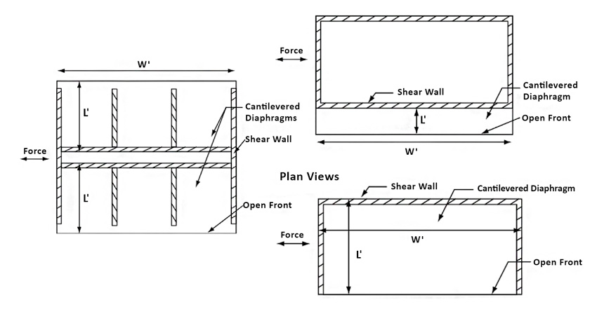
Image courtesy of the American Wood Council
Figure 5: Three-Sided Open-Front Structures
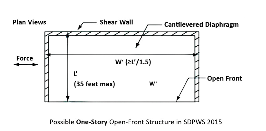
Image courtesy of the American Wood Council
Image courtesy of the American Wood Council
Figure 5 illustrates an example of what’s possible for single-story, low-rise, open-front building types with shear walls only on the back wall. The maximum length of the roof from the open front to the back shear walls (L') is 35 feet. The width (W') of such a one-story building is allowed to be equal or greater than L', so square (e.g., L'=35 feet, W'=35 feet) and long (e.g., L'=35 feet, W'=200+ feet) buildings are possible using this approach. In some cases, narrow buildings with W' not less than L'/1.5 (e.g., L'=35 feet, W'=23.3 feet) are possible. For exact requirements, designers should refer to the SDPWS. Such open front buildings may be useful for smaller retail or office buildings. With a building deeper than 35 feet, options include adding an interior shear wall line to reduce the cantilever length to 35 feet, or placing shear walls or other lateral force-resisting elements along the front side of the structure.
Roof Framing
There are many wood options available to achieve the long spans typical of commercial building roofs.
Truss Roofs
Although trusses are often associated with the pitched roofs of single-family homes, they come in a seemingly infinite range of profiles and sizes, with some spanning over 80 feet. Trusses are strong, quick to install, and economical. They’re also highly versatile. Designed using sophisticated software, they can be manufactured in complex shapes and unusual configurations, accommodating arches, for example, or enabling companies to incorporate features distinct to their branding. They’re also compatible with other materials, and their open-web configuration allows easy placement of mechanical, electric, and plumbing (MEP) services.
Designers can choose from metal-plate connected wood trusses or timber trusses. Metal-plate connected wood trusses are made from dimension lumber joined together with metal connector plates and are among the most economical wood roof systems. Timber trusses can be made from solid or engineered wood members. They are highly engineered and typically left exposed as an architectural feature.
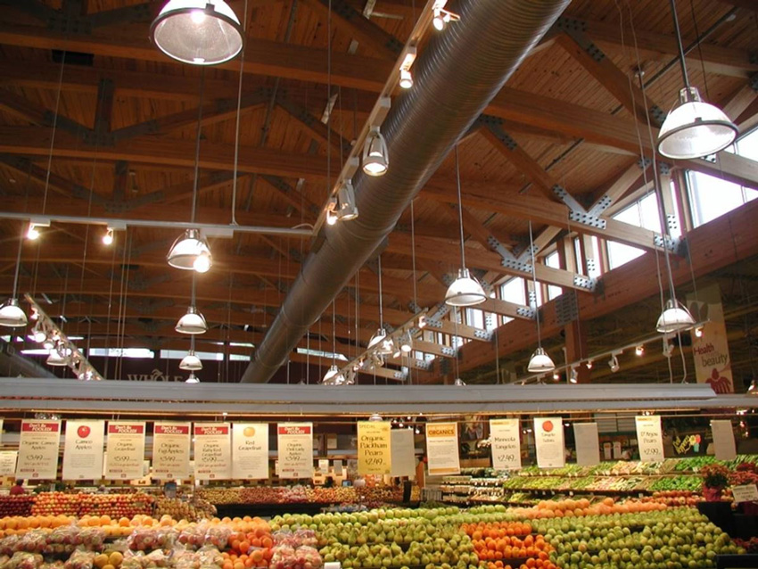
Photo: Scott Lockyear, WoodWorks
The roof of this 15,000-square-foot Whole Foods Market in Atlanta, Georgia, spans 67 feet. It is comprised of 60-inch-deep glulam trusses spaced 14 feet apart, 2-by-6 tongue and groove southern pine planks supported on glulam beams, and 8-by-8 columns at 20 feet on center.
I-Joist Roofs
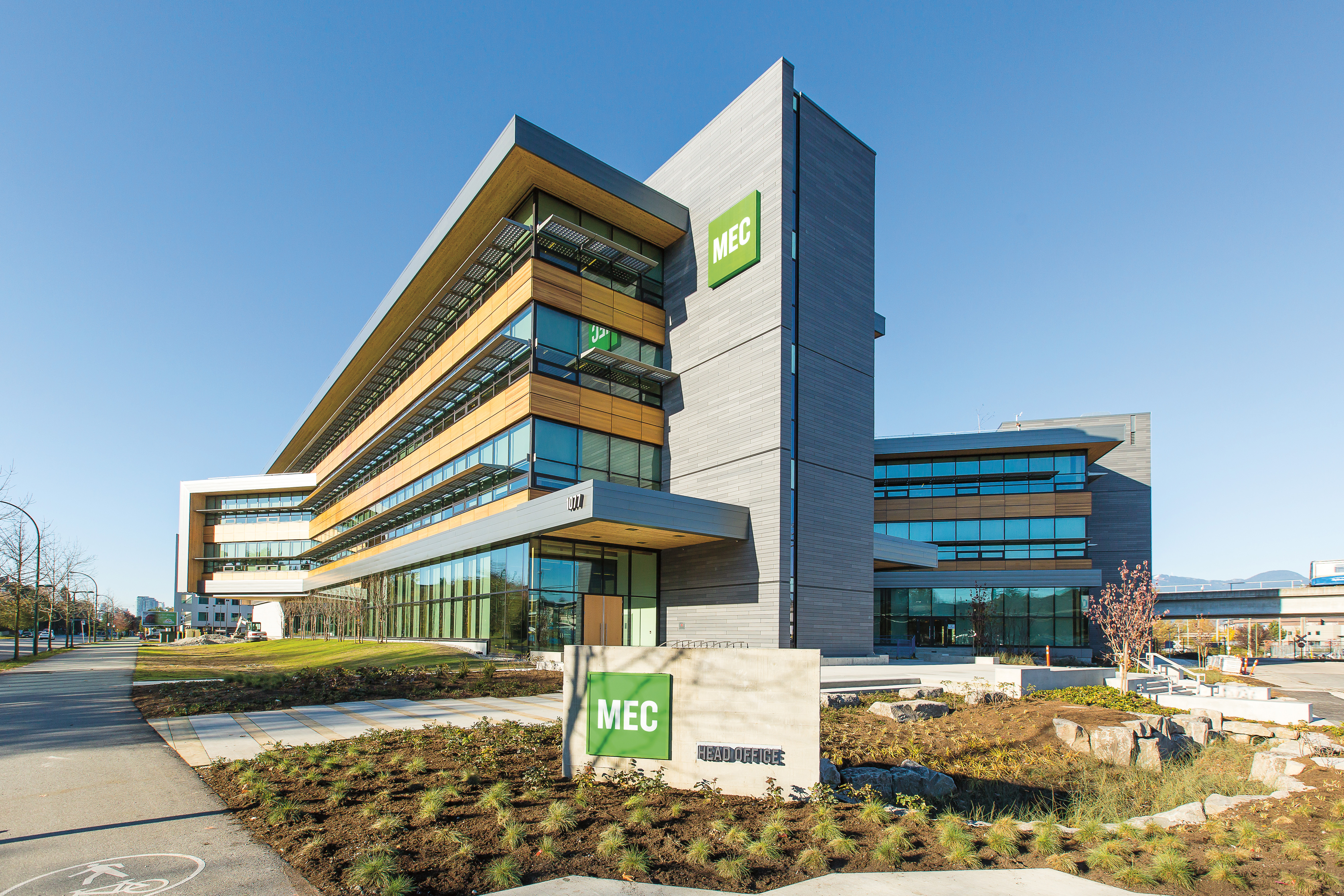
MOUNTAIN EQUIPMENT CO-OP (MEC)
Location: Vancouver, British Columbia
Architect: Proscenium Architecture + Interiors
Engineer: Fast+Epp Structural Engineers
Photo: KK Law
Canada's biggest retailer for outdoor gear chose wood for its environmental and biophilic benefits. The structure is constructed with laminated timber beams and columns, joined and braced with steel fittings. A double-beam configuration serves double duty; the exposed beams give warmth and architectural interest to the interior and their increased stiffness reduces deflections and floor vibrations.
I-joists are comprised of top and bottom flanges, which resist bending, united with webs, which provide excellent shear resistance. The flange material is typically solid sawn lumber or LVL, and the web is made with plywood or oriented strand board (OSB). I-joist framing is commonly used for flat and low-slope roofs with spans up to approximately 30 feet. Sloped roof applications also provide vaulted ceiling opportunities.
In one common configuration, wood I-joist roof systems are framed with a central bearing wall or beam that carries roof loads to the posts. Loads from the top half of the roof are carried by the bearing wall or beam, and loads from the bottom half are carried by exterior bearing walls. Loads are primarily gravity loads, which push down, not out, on the bearing walls.
Information on design and installation of I-joist roofs can be found in the APA publication, Performance Rated I-Joist Roof Framing Details, and AWC’s Manual for Engineered Wood Construction.
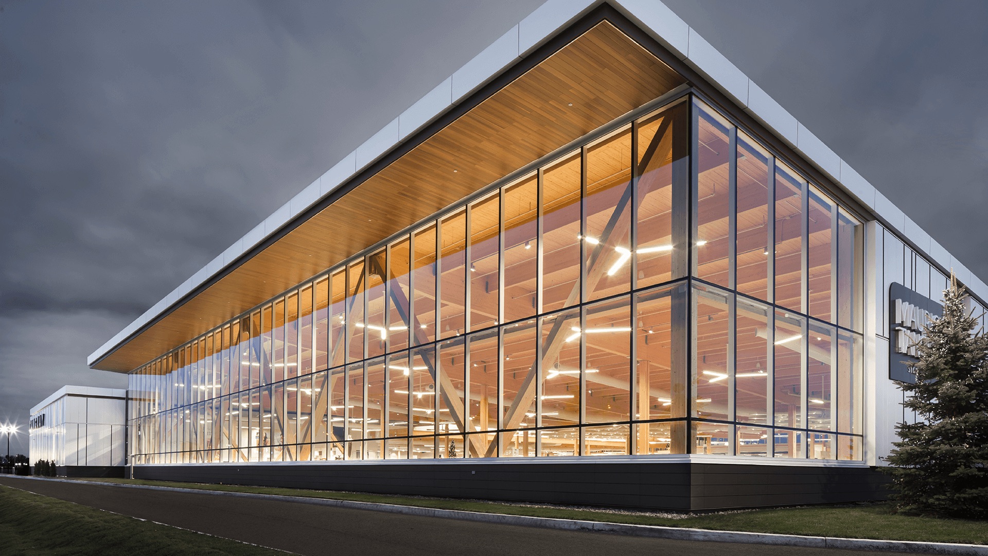
TANGUAY FURNISHINGS
Location: Trois-Rivières, Québec
Architect: Coarchitecture
Engineer: Nordic Structures
Photo: Stephane Groleau courtesy Nordic Structures
Glued-laminated timber (glulam) post-and-beam construction serves as the primary structure for this 80,000 square-foot retail furniture showroom. Glulam decking forms the expansive ceiling while a cedar soffit gives the interior and exterior structures visual continuity. The long-spanning 50-foot beams provide the customer with uninterrupted views of merchandise and facilitate enhanced wayfinding.
Large, Flat Roof Systems
For large projects such as grocery or big box retail stores—which can have grid dimensions of 45 feet by 50 feet or larger—panelized roof systems can be a cost-effective solution. According to one roof erector, panelized wood roofs on the West Coast can save $1.25 to $1.50 per square foot over conventional steel joist metal deck systems.2 Savings can be attributed to, among other things, material costs, speed of installation, and insulation. This is also supported by the cost comparison described in the sidebar, Big Box Retail: Wood Saves Nearly $1 Million.
In North America, both all-wood and hybrid panelized roof systems are common.
All-wood systems tend to be used for spans of 40 feet or more, and are particularly well-suited for applications where conveyer equipment is hung from the roof structure or in food processing facilities that need to minimize dust from overhead joists. They are also a good choice for developers and designers who want to take advantage of wood’s aesthetic benefits for an exposed roof structure.
In a typical all-wood system, sheathing or wood structural paneling spans between sub purlins, which are 2-by-4 or 2-by-6 dimension lumber, depending on the span. Sub purlins span between purlins, which can be glulam, I-joists, metal-plate connected wood trusses, or wood flange metal web trusses, and the purlins span between girders, or girders and exterior walls. Girders are typically glulam beams, either simply supported or with cantilevers. That said, there are many possibilities for the design of large, flat wood roofs, including options with no sub-purlins but longer-spanning decking products, such as tongue and groove timber or laminated decking and mass timber.
Parapets are a common feature of many flat roofs, providing space for signage and hiding mechanical units. Framing options include:
- Tall stud parapets, where the wall framing extends past the roof frame so the parapet is a continuation of the studs themselves
- Built-up parapets, where the studs stop at the top of the wall and the parapet is built on the roof (requires bracing)
- Truss parapets, where the parapets are built into the trusses themselves during manufacture
For large, flat roof applications, unlimited areas can be achieved under IBC Section 507. However, designers of low-rise commercial and industrial applications may also design large roofs under standard provisions of IBC Chapter 5 using sprinkler increases and the sub-notes included with IBC Table 601.
The SDPWS includes information on high-load diaphragm design useful in panelized roofs. High-load wood diaphragm design with multiple rows of nails (accommodating ASD capacities up to approximately 1,500 plf for seismic and 2,000 plf for wind) is possible in configurations using tall and/or heavy wall systems, especially in combination with very large diaphragms.
SUPPORTING COMMERCIAL WOOD BUILDING DESIGN
For individuals involved in the design, construction, review, and approval of commercial buildings, WoodWorks and the American Wood Council offer a variety of resources at no cost.
For more detailed information on the subjects covered in this CEU, a new version of the American Wood Council’s Code Conforming Wood Design based on the 2018 CCWD is available as a free download at www.awc.org.

Project support: WoodWorks provides free project assistance, as well as education and resources related to the code-compliant design, engineering, and construction of nonresidential and multifamily wood buildings. www.woodworks.org

Codes and standards support: Expert staff at the American Wood Council develop state-of-the-art engineering data, technology, and standards for wood products to assure their safe and efficient design. They also provide information and education on wood design, building codes, and green building. www.awc.org
End Notes
1“Big Box Retail: Wood Saves Nearly $1 Million.” (2015): 1-12. WoodWorks Case Study WW-019: Big Box Retail Comparison. WoodWorks,
www.woodworks.org/wp-content/uploads/Big-Box-Retail-Wood-vs-Steel-Oct-2015.pdf
2“Faster, Safer, Lower Cost: Panelized Roof Systems.” (2012): 1-8. WoodWorks Case Study WW-008: Panelized Roof Systems. WoodWorks, www.woodworks.org/wp-content/uploads/IS-Panelized-Roofs.pdf
|
|
Think Wood is a leading education provider on the advantages of using softwood lumber in commercial, community and multifamily building applications. We introduce innovators in the field to our community of architects, engineers, designers and developers. For support or resources, contact us at info@ThinkWood.com. |
