Roofs for Cold Storage Buildings


Details
All of these concepts—moisture and vapor drive, thermal control—come together at the intersections of systems (e.g., roofs and walls) and penetrations, and these are the locations that should have construction details developed for use during the bid phase and certainly during the construction phase.
Thermal efficiency considerations include multilayer insulation, where fasteners and adhesives are located within the system. Designs with the first layer attached and the upper layers adhered is shown to be most effective.9 Because air leakage is an important part of energy efficiency, consider the direction of the vapor and air drive; when placing the air barrier on the exterior, it’s important to locate the air seals toward the exterior so they are positioned to be the first line of protection against air infiltration.
Consider expansion and contraction as well as differential movement. Cold storage buildings can experience a larger temperature differential from interior to exterior given the low interior temperatures, relative to typical office buildings that have interior temperatures of approximately 70 degrees Fahrenheit.
Using insulation with high R-value per inch reduces the total insulation thickness. This may also reduce the length of fasteners, depending on attachment design. One way to eliminate the need for tapered insulation is to slope the structural deck.
Considering the location and constructability of the connections and tie-ins for the air-barrier details is long-term risk management. The roof membrane is the vapor-control layer and the air-control layer for the primary vapor and air drive for cold storage buildings. Of the two, the air-control layer is more critical for long-term success.
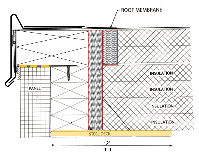
Special attention should be paid to steel roof decks, which are used in a large number of cold storage buildings, because they pose a detailing issue regarding air control. It’s challenging to air-seal steel roof decks at walls and penetrations. Deck flutes can serve as “conduits” or pathways through which air and air-transported moisture can flow. To minimize airflow, flutes can be filled with closed-cell spray polyurethane foam (SPF) at walls and penetration locations. Figure 7 is an example of a roof-to-wall construction detail showing SPF used to create a continuous air barrier from the wall to the roof.
Detail courtesy of Matt Dupuis, SRI
FIGURE 7: Shown is the use of spray polyurethane foam as the tie-in from the roof air barrier to the wall air barrier.
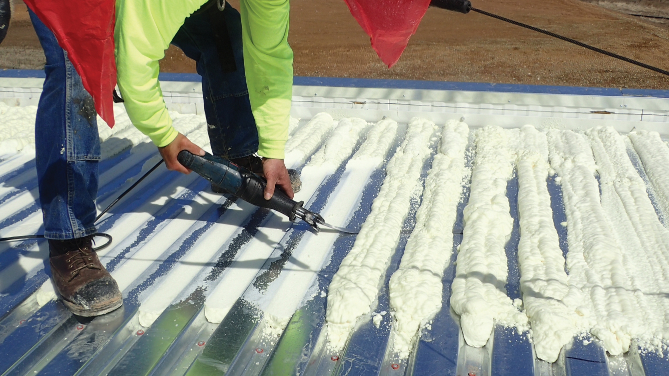
Photo courtesy of Matt Dupuis, SRI
PHOTO 3: Shown is the installation of spray polyurethane foam in the flutes of a steel deck.
It’s important to recognize that a steel deck meets a wall with two different profiles because its profile is not the same in each direction. The foam may need to extend 1–4 feet along the flutes when the flutes are perpendicular to the wall to prevent the communication of air from the roof to the wall, which can result in interior icicles. When flutes are parallel to the wall, perhaps only the first flute or two needs to be filled. Two construction details are needed to ensure that air is properly controlled at the roof-to-wall intersection.
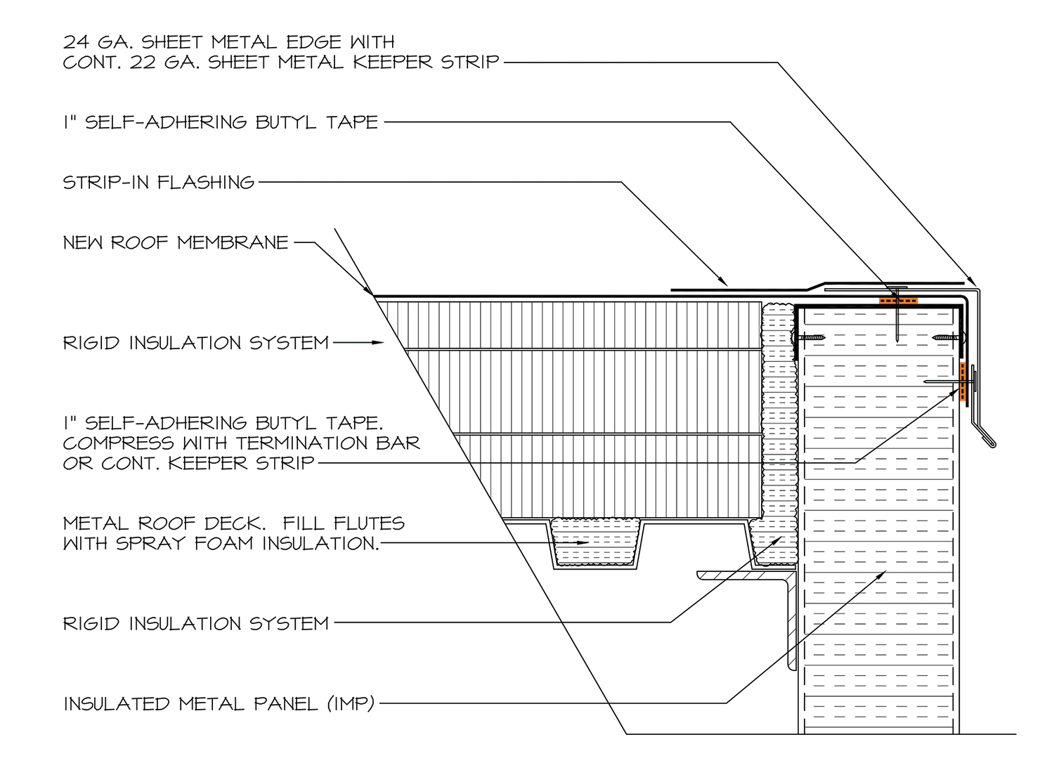
Wood blocking is often used at roof edges to create a robust edge for securement of the edge metal. However, the thermal resistance (per inch) of wood blocking is low relative to the primary insulation used in the roof and walls, certainly for IMWPs. The wood blocking is, relatively speaking, a thermal discontinuity. Proper air sealing is important at areas of reduced R-value to reduce the potential for air-transported moisture to reach locations where it will condense. The use of non-curing butyl tape between the top of a wall panel and the underside of the wood blocking, in conjunction with closed-cell spray foam (ccSPF) in the flutes and between the stack of wood blocking and the ends of the rigid insulation creates a roof-to-wall element that effectively continues the air barrier from the roof to the wall. Figure 8 is a good example of this condition.
Graphic courtesy of GAF
FIGURE 8: Shown is wood blocking used as a robust edge condition to secure the edge metal. Proper air sealing is important at areas of reduced R-value.
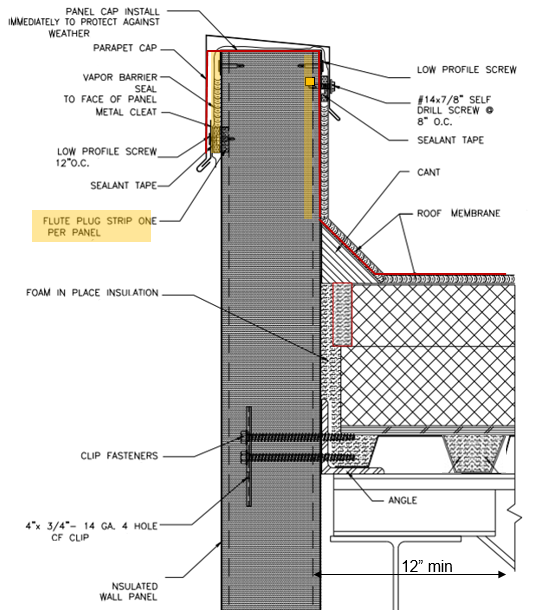
Raised roof edges are often the result of using balloon framing construction methods, such as IMWPs extending vertically past the roof deck, the insulation, and membrane flashing (see Figure 9). A raised roof edge is commonly protected by a metal coping. The flashing membrane is extended up, over and down the face of the raised roof edge. In this scenario, the outer face of the IMWP is considered to be the air barrier.
Air seals are needed at the metal deck where it meets the wall and support angle, and air seals are needed between the face of the IMWP and the edge of the insulation boards. This is a critical location for air leaks and condensation potential. Leveraging SPF materials provides a constructible detail. Also, air sealing is needed between the membrane and each face of the IMWP when installed as a raised roof edge. In this scenario, air-leakage control is necessary on both surfaces of the IMWP. This brings two considerations into play for air sealing.
First, the joints between the IMWPs need to be air sealed. Left unsealed, the joints are a direct path from the exterior to the roof deck and roof insulation. This is an important location to air seal properly. It’s not good practice to only rely on the outer (exterior) seal to be the air barrier. Importantly, the vertical joint between IMWPs is a path for air leakage and intrusion. Breaches to any portion of the exterior seal will allow air to move between the panels and within the vertical joint, which can easily reach the raised roof edge. Therefore, the interface between the roof and IMWP must be sealed on the interior side as well. An air seal on the outer and inner surfaces—a double air seal—is an excellent way to block air exfiltration and infiltration. If these joints are not air sealed, they can allow airflow and the moisture and heat it holds to bypass the air-control layer and enter the building. These same considerations are true for precast concrete wall panels that are installed outboard of the roof deck and extend vertically past the completed roof system.
Second, when using a corrugated IMWP, the corrugations are difficult to air seal. Specifying the use of flute plugs that “fill in” the corrugations allows for a successful air seal between the surfaces of the metal wall panel and the air-barrier membrane (e.g, the roof membrane). During installation of the roof membrane, ensuring the roof membrane extends far enough over the perimeter edge to allow for proper termination and continuity is important. And let’s not forget the basics: Staggering and offsetting the board joints between the multiple layers of insulation provides for some air control.
Graphic adapted from Metl-Span
FIGURE 9: Shown is a raised roof edge with air seals between roof and wall, as well as flute plugs where the membrane wraps over and down the exterior of the IMWP.
For these and other constructability issues, onsite mockups can be helpful to work out detail specifics and workmanship issues prior to final construction. The construction and testing of mockups should be in the construction documents and specified so there are no surprises.
There often are different conditioned spaces within a single facility. Offices and loading docks are often part of a cold storage building. These spaces should be separated thermally and should not allow air movement from space to space. That means ensuring there are air seals and continuous insulation at the intersection of outer walls and the roof, and given the different interior environments, also at the intersection of inner walls and the roof.
To accomplish this separation of conditioned spaces, a membrane strip can be turned down through the insulation layer and adhered to the deck. This type of detail prevents lateral airflow from the roof above a warm office space into the roof above a colder cooler or freezer portion of the building. For steel decks, flutes should be filled to prevent lateral airflow, especially when the flutes of the metal deck are perpendicular to the separating wall. For solid decks, an air seal (e.g., butyl tape) should be used to seal the membrane to the deck. Photo 4 and Figure 10 show this detail as built and as designed.
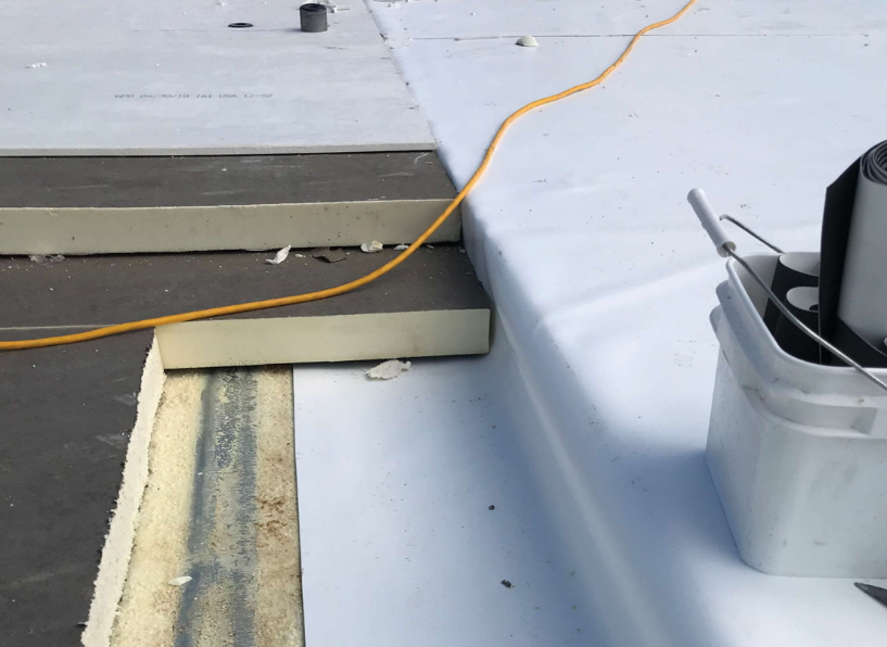
Photo courtesy of Matt Dupuis, SRI
PHOTO 4: Shown is a roof membrane through insulation and adhered to roof deck to prevent lateral air movement.
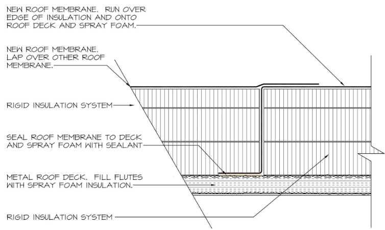
Detail courtesy of Matt Dupuis, SRI
FIGURE 10: Shown is a roof membrane through insulation and adhered to roof deck to prevent lateral air movement.
If the interior wall extends higher than the roof deck (essentially separating two roof areas), not only does air infiltration need to be minimized or eliminated, but there is also the potential for thermal bridging at this location. Figure 11 shows this configuration. The top layer of insulation and the membrane should be adhered to reduce the thermal bridging potential of the fasteners and plates. An intentional gap between the IMWP and the roof insulation allows for the use of ccSPF to prevent lateral air movement. Again, where the metal deck flutes are perpendicular to the separating wall, filling the flutes with spray foam helps prevent lateral air movement.
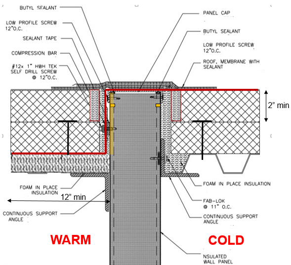
Graphic adapted from Metl-Span
FIGURE 11: Shown is a separating wall between two differently conditioned spaces.
Another way to help reduce thermal bridging where an IMWP extends to the underside of the roof membrane is to make a saw cut on both sides of the metal panel. This literally disrupts the thermal bridging of the metal skin of the IMWP. Placement of the cut matters; if it’s too far down the panel, structural issues could arise. The specific IMWP manufacturers can provide guidance on the best location and depth of the cuts to limit thermal bridging.
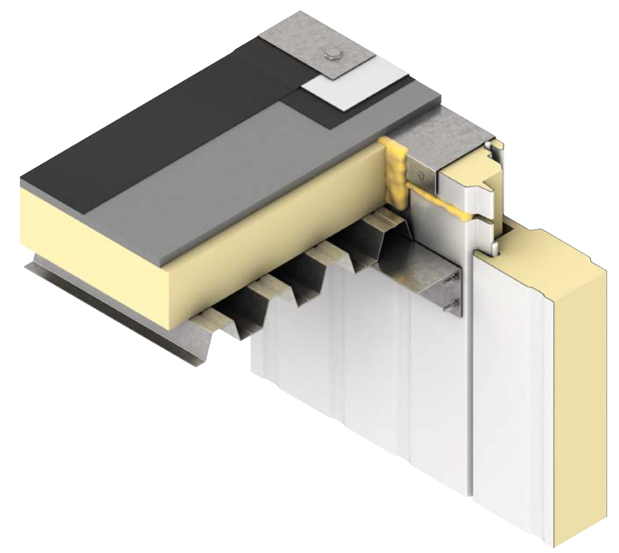
Image courtesy of Kingspan
FIGURE 12: Shown is a saw cut in the metal skin of an IMWP to reduce thermal bridging.
Penetrations in the field of the roof are potential locations for air leakage, thermal loss and condensation. An equivalent effort to air seal should be made at penetrations in the field of the roof as is made at the perimeters where the roof meets the wall. Typical details often do not specifically address air sealing, and certain details like ganged penetrations are difficult to air seal.
Standard details typically show the insulation butting up to a vertical penetration, like a pipe. The addition of spray foam between the edges of the insulation and the penetration makes an effective air seal at that location. The air-control layer should be connected to the spray foam to provide a continuous air barrier; for cold storage buildings, the air seal around the pipe should tie to the roof membrane that is acting as the air-barrier-control layer. Figure 13 shows this condition.
Pipes in roofs and walls may move due to thermal expansion and contraction as well as vibration, so it’s important to select pipe penetration flashings that can accommodate movement, such as pre-manufactured flashing boots. Figure 13 also shows this idea.
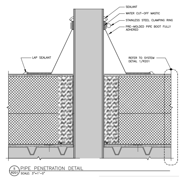
Graphic courtesy of Roof Spec Inc.
FIGURE 13: Shown is air sealing around a pipe penetration and a flexible pre-molded flashing boot.
Curbs are also potential locations for air leakage, thermal loss and condensation. Again, proper air sealing at curbs is important for long-term performance. However, the rooftop unit may allow airflow. Continuing the air-barrier layer up the vertical wall of the insulated curb isolates the rooftop unit from the roof system.
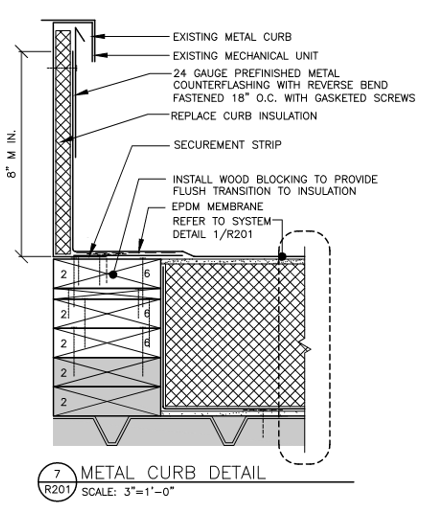
Graphic courtesy of Roof Spec Inc.
FIGURE 14: Shown is air sealing around a rooftop curb.
A continuous air barrier is a combination of interconnected materials and systems that require sealed joints and connected components to properly minimize air leakage into or out of the building enclosure. During the design process, architects can use the pen test to trace the air-barrier layer around the entire building (without picking up the pen from the paper), focusing on the perimeters and penetrations, and subsequently addressing the details in the contract documents, to help determine where potential air leakage may occur.10 Ultimately, the architects and designers are responsible for determining the need for an air barrier, verifying an air barrier’s compatibility with other materials, identifying all air-barrier components of the enclosure, and providing construction details for joints, penetrations and transition areas.
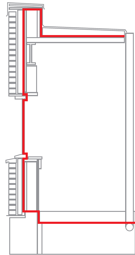
Graphic courtesy of GAF
FIGURE 15: Shown is a continuous air barrier that can be traced by using a pen without picking up the pen from the paper.
