Exceeding Thermal Performance Goals by Choosing Wood


Strategies for Improved Performance with Wood
The natural properties of wood make it a great insulator. When used in conjunction with aggressive insulation strategies, wood can enable an architect to design a building with exceptional thermal performance. To maximize building performance with wood, we will take a look at three aspects of improving a building’s thermal performance: identifying the paths of heat transfer, creating more space for insulation, and creating an aggressive air and moisture barrier.
Limiting Heat Transfer Through Walls
While most heat loss occurs around windows and penetrations in the building envelope, when designing with wood, it is important to look at all aspects of the design to ensure a complete building enclosure strategy. For instance, wall design offers many opportunities to improve the thermal performance of the building, but first you must identify where heat transfer is most likely.
Source: The Role of the Structural Engineer in Net-Zero-Energy Construction
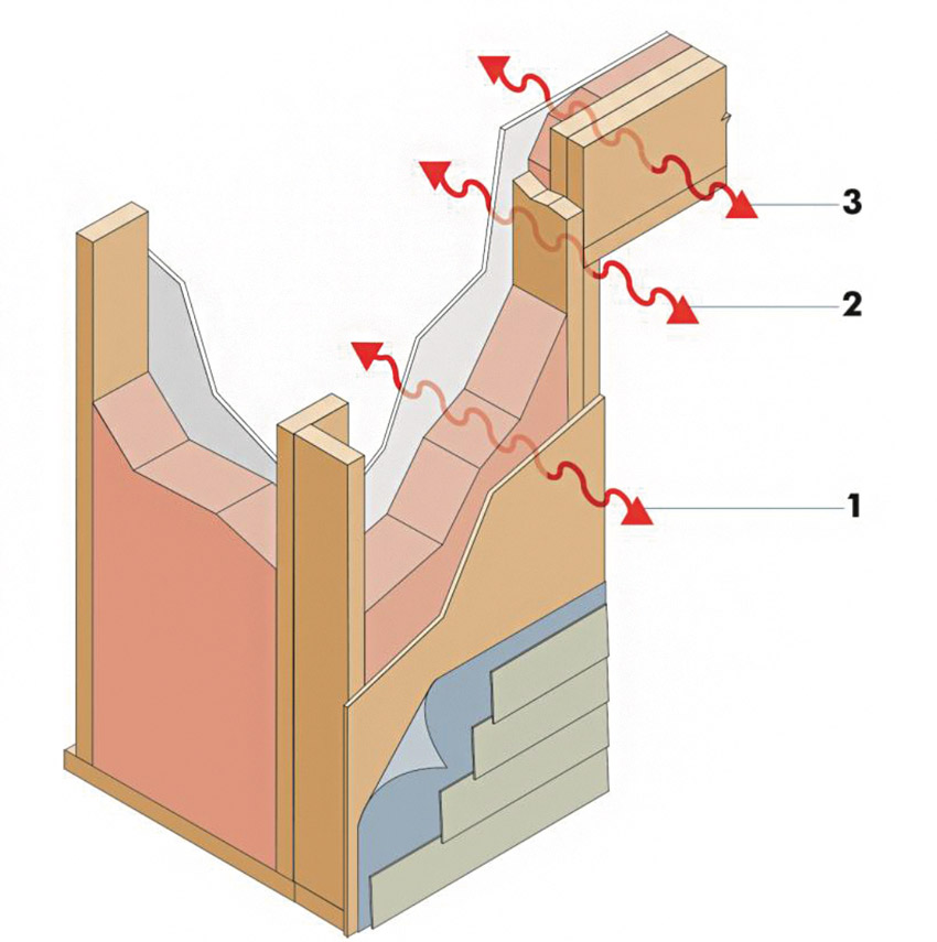
Heat transfer occurs through the cavity insulation, framing members, and headers.6 The three locations offer parallel paths for heat transfer.
Heat transfer occurs through the cavity insulation, framing members, and headers. The three locations offer parallel paths for heat transfer.6
Transfer through the cavity insulation has the most heat resistance due to the absence of framing. With wood included in the design process, this area offers an opportunity to increase overall R-values. Increasing cavity gap by using 2-by-6 studs, employing advanced framing strategies, and staggering stud design are all successful ways to reduce heat transfer through the insulation cavity.
Framing members include studs, top and bottom wall plates, and full-cavity width blocking. Strategies to reduce heat transfer through framing members include incorporating intersecting wall techniques and energy-efficient corners, such as three-stud corners and ladder junctions, that allow for greater insulation volume. Energy-efficient headers and limited framing around openings as well as eliminating double top plates are also effective strategies. Note that eliminating double top plates has its challenges. This step requires vertical framing alignment, including 24-inch-on-center floor and roof framing as well as non-industry standard stud lengths that may be difficult to source. In addition, the use of a single top plate requires metal straps for tension splices, which can contribute to significant thermal bridging.
The third area of heat transfer in walls is through the framing headers that carry structural loads above window and door openings. To improve the thermal performance of headers, more insulation is usually used. Reducing the amount of framing material in headers can be done through use of engineered lumber or single-ply sawn lumber, but care must be taken to ensure the integrity of the load path.
Creating Effective Air Barriers
The control of air leakage is important to conserve space heat and reduce air-conditioning loads. In multistory buildings, air leakage may account for up to half of the space heat loss, depending on the air-leakage rate, building height and wind exposure, occupant behavior, mechanical penetrations, and several other factors, including the enclosure thermal performance.
Air leakage in multistory buildings is typically higher than in smaller, single-family dwellings due to increased wind exposure, the stack effect, and mechanical systems, all of which contribute to higher and more sustained differential pressures across the building enclosure.
Controlling air flow through the use of air-barrier systems is important to minimize the loss of conditioned air through the building enclosures, along with other factors. Air-barrier systems are required for all multiunit residential buildings in all climate zones.
The air barrier is the means of preventing air leakage through the building envelope. A building’s air barrier should be continuous, integrating all the exterior envelope systems—the wall air barrier with the roof air barrier, and so on. The air barrier can be installed on the interior or exterior of the building envelope. An efficient and cost-effective way to achieve an effective air barrier on walls is to incorporate a continuous, solid layer on the exterior of a building. The continuous solid material should be stiff enough to minimize the amount of deflection when pressure is applied to tape or sealants in order to create an effective seal on panel joints and around wall penetrations. Panel joints need to be properly sealed to complete an air-barrier assembly.
Continuous wood structural panel sheathing is commonly used as part of an air-barrier system for exterior walls. The architect typically details how panel joints and openings are to be sealed—usually with tape or sealant specifically recommended for use on plywood or oriented strand board (OSB). Using continuous structural sheathing as part of the air-barrier system also provides a solid support base for exterior cladding systems while increasing the structure’s earthquake and wind resistance.
When using continuous wood structural panels as the air barrier, panels should not be glued directly to framing. This approach is restricted in high Seismic Design Categories per the American Wood Council’s Special Design Provisions for Wind and Seismic (SDPWS) Section 4.3.6.1. Gluing wall sheathing to framing also restricts wood panels from expanding as moisture is absorbed, which can contribute to out-of-plane buckling.
Make sure that any sealant or tape used to complete the air barrier does not impede the ability of the panels to expand when exposed to increased humidity in the wall cavity or wetting due to construction delays. Anything that prevents panel expansion into the recommended ⅛-inch spacing between panels could result in buckling of the wall sheathing. Also, make sure the tape is rated for use as part of an air barrier system.7
A water-resistive barrier, such as housewrap, should always be installed over wood structural panel wall sheathing in order to direct any moisture that penetrates the cladding away from the sheathing and wall cavity.
Unlike vapor barriers, there is little to no downside of redundancy in the air barrier provided the materials used do not negatively impact vapor flow. In fact, some designers incorporate more than one continuous air barrier—one on the building interior and one on the exterior.
Managing Water in the Building Envelope
Similar to controlling air movement, the flow of water in wood-framed buildings must be controlledin the building envelope. Water can ruin insulation, create rot and structural issues, and is the key ingredient contributing to mold growth and associated indoor air quality issues. Water vapor condensation is a major threat to the structure of a house no matter the climate or framing material. In cold climates, pressure differences can drive warm, moist indoor air into exterior walls and attics. The air condenses as it cools. The same can be said for southern climates, just in reverse. As the humid outdoor air enters the walls and encounters cooler wall cavities, it condenses into liquid water.
In most U.S. climates, vapor barriers, or—more accurately—vapor diffusion retarders, should be part of a moisture-control strategy for a home. A vapor barrier or vapor diffusion retarder is a material that reduces the rate at which water vapor can move through a material. The older term “vapor barrier” is still used even though “vapor diffusion retarder” is more accurate. How to design and install vapor retarders depends a great deal on the climate and the chosen construction method. However, a universal truth of building envelope design is that any water vapor that does manage to get into the walls or attics must be allowed to escape.
In mild climates, materials such as painted gypsum wallboard and plaster wall coatings may be enough to impede moisture diffusion. In more extreme climates, higher-perm vapor diffusion retarders are advisable for new construction. They perform best when installed closest to the warm side of a structural assembly—toward the interior of the building in cold climates and toward the exterior in hot/wet climates.
A vapor diffusion retarder installation should be continuous and as close to perfect as possible. This is especially important in very cold climates and in hot and humid climates. Be sure to completely seal any tears, openings, or punctures that may occur during construction. Cover all appropriate surfaces or you risk moist air condensing within the cavity, which could lead to dampened insulation. The thermal resistance of wet insulation is dramatically decreased, and prolonged wet conditions will encourage mold and wood rot.
Combining air barriers and vapor diffusion retarders is becoming more popular, especially in warmer humid climates. An air barrier/vapor diffusion retarder system attempts to accomplish water vapor diffusion and air movement control with one material. This type of material is most appropriate for southern climates where keeping humid outdoor air from entering the building cavities is critical during the cooling season.
In most cases, air barriers/vapor diffusion retarders consist of one or more of the following—polyethylene plastic sheets, foil, foam board insulation as part of a continuous insulation design, and exterior sheathings. Air barriers/vapor diffusion retarders typically are placed around the perimeter of the building just under the exterior finish, or they may actually be the exterior finish. The key to making them work effectively is to permanently and carefully seal all of the seams and penetrations, including around windows, doors, electrical outlets, plumbing stacks, and vent fans.
