New Innovations in Vertical Air Conditioning


The platform is designed to integrate with the wall plenum and align the chassis with the plenum gasket for a tight seal. In the past, these platform installations required more complex customized construction, but the new system is a one-piece design that can adjust and be tailored to a given location. Because it can easily be installed, it eliminates the necessity of skilled-labor requirements.
The system is designed to allow the installation of the chassis from the front or either side of the closet. This provides greater flexibility in building and room design and unit placement. If access to the front of the unit is restricted by a wall or furniture placement, the chassis can slide in from either side of the closet. If an alcove or offset is designed into the building facade, the three-way slide-out chassis enables the unit to be easily installed and removed for service.
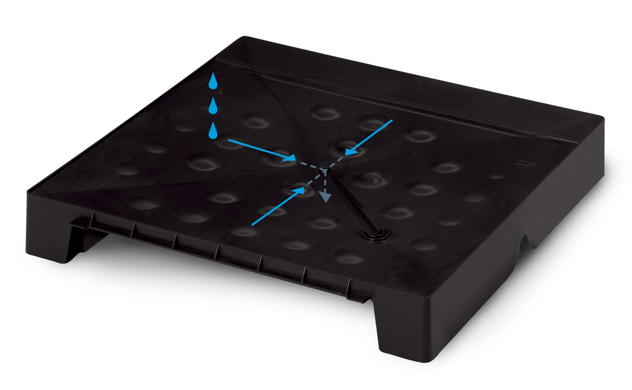
Easy installation of the self-contained drainage system allows for simple chassis removal while leaving plumbing completely intact.
The platform includes a self-contained drainage system and features notches on each side and the front of the platform for the primary drain to exit. This feature allows flexibility in plumbing connections and adapts to varying site conditions. Easy installation allows for simple chassis removal while leaving the plumbing completely intact.
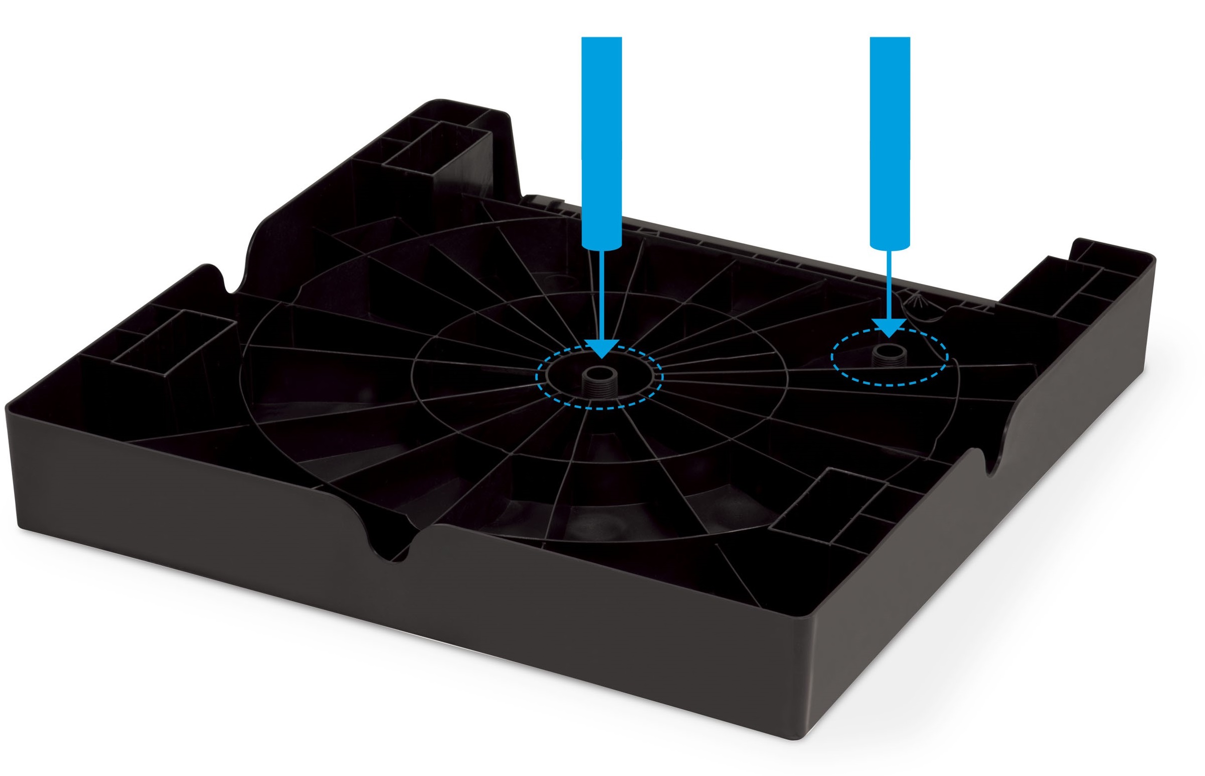
The fast-connect plumbing design has threaded plumbing fittings can be used to attach primary and secondary drain fittings to the platform.
The VTAC design has simple, easy-to-install plumbing. Easy use threaded plumbing fittings can be used to attach primary and secondary drain fittings to the platform. In this type of system, the primary drainpipe needs to be 12.5 inches long to extend beyond the platform so it can easily be connected to the building drain line, while the secondary drainpipe (which goes into the plenum) should be no longer than 8 inches to allow for the platform to attach easily to the wall plenum. Two 2 x 4 supports, which can be cut to size, are placed in pockets under the platform on the side opposite the plenum. Measure from the floor to the bottom of the side flange of the plenum and then add 3 inches to determine the length of the 2 x 4 supports. With the primary and secondary drain fittings installed, as well as two 2 x 4 front supports installed, the platform assembly can be integrated with the wall plenum. Holding the platform at approximately 15°, align the locking pins and tabs of the platform to the corresponding holes and slots in the plenum. Then, lower the plenum until the 2 x 4 supports meet the floor in a level position.
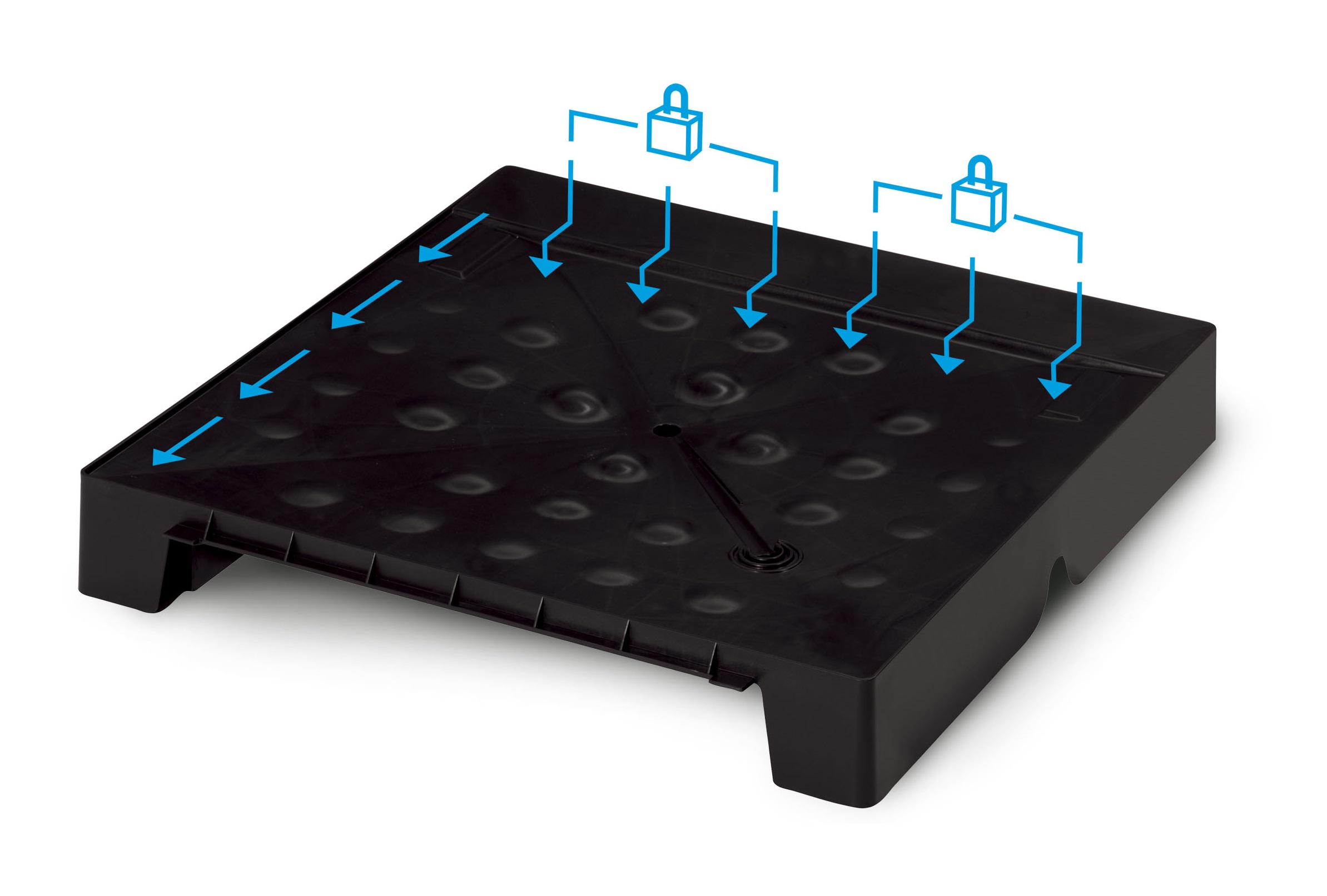
The locking ledge of the self-aligning system secures the chassis to the platform for a perfect fit and seal.
Then, the chassis can be installed onto the platform. The locking ledge technology of the self-aligning system provides a nearly foolproof installation experience. The locking ledge secures the chassis to the plenum gasket in a near-perfect fit and seal without any fasteners.
Those main features — wall plenum, platform, drainage system, easy plumbing, and self-aligning technology — are key to making the VTAC unit a process that doesn’t require skilled labor. After these elements of the system are in place, remove the junction box cover from the chassis and locate the thermostat connector. Connect the thermostat connector wires to the field-supplied thermostat cable and use the instructions to determine the proper connection to the thermostat connector. Once the connections are complete, plug in the thermostat connector to the chassis. With the thermostat connected, use the round knockout hole in the top of the junction box to install the power wiring (or flex cable) coming from the branch circuit. Leave 8 inches of extra wire inside the junction box for the final electrical connection. Install the proper power supply kit matching the voltage and amperage of the branch circuit. When the wiring connections are complete, plug in the power connector and the personality plug. Reinstall the junction box cover.
Using a field supplied clamp, secure the flexible 10-inch duct to the discharge duct flange on top of the unit. Use a clamp to secure the other end of the flex duct to the air discharge box above the unit and finally, install the filter.
The unit is ready for operation at this point, but there are still more features to discuss that elevate this new technology above older vertical air conditioning units: ultra-quiet performance, reverse-cycle defrost, seacoast protection, onboard diagnostics, and smart Wi-Fi capability.
