Parapets—Continuity of Control Layers


Energy Efficiency for Parapets
Generally, within the IBC it is required that a building be “designed and constructed in accordance with the IECC 1301.1.1.” The IECC has both residential and commercial provisions, and the commercial provisions apply to “all buildings except for residential buildings 3 stories or less in height.” The IECC is structured in a way that provides the option of either complying with the prescriptive requirements within it or by complying with the alternate ASHRAE 90.1 energy standard.
Compliance Alternatives: The IECC has multiple compliance paths within it, including:
- Either following the prescriptive requirements within the IECC or ASHRAE 90.1, or
- Following the performance modeling requirements of ASHRAE 90.1 Appendix G.
The prescriptive options within both the IECC and the reference standard ASHRAE 90.1 primarily regulate energy use by providing lists and itemized requirements. These can be helpful when the building is straightforward and tradeoffs don’t need to be made. When a building is more complex, has specific energy usage demands, or if an owner wants to demonstrate energy compliance beyond code, the performance path within ASHRAE 90.1 Appendix G is the methodology required. For example, any modeling being performed to show compliance with LEED is being performed to comply with Appendix G in ASHRAE 90.1. A growing method of compliance is whole-building design energy modeling and on-site performance testing happening in new construction. When an existing building is reroofed, the designer will most likely follow the prescriptive path to determine the amount of insulation to use.
Insulation: The insulation requirements in the table include both cavity and continuous insulation, but vary based on the framing material (IECC C301.1 & 90.1 Annex 1). Including continuous insulation in both the walls and roof systems of the parapet helps manage thermal bridging across the assemblies. The prescriptive tables in the energy codes dictate minimum R-values in the roofs and walls based on the climate zone of the project site, the building use, and the framing materials of the wall and roof system. As described earlier in the thermal control discussion, the framing materials matter in the prescriptive requirements, especially when insulation is placed between framing members in parapet cavities.
For more complex details like a parapet, the energy code doesn’t get into separate requirements for the insulation. The codes generally require that continuous insulation be depicted in the construction documents with sufficient clarity to indicate the location, extent of the work and show sufficient detail for continuity of the thermal control layer. Per the IECC (C103.2), insulation continuity for complex conditions should be shown in the details.
Air Barrier: ASHRAE 90.1 defines a continuous air barrier as a “combination of interconnected materials, assemblies, and sealed joints and components which together minimize air leakage into or out of the building envelope.” It’s a good definition and an accurate description of what is needed to have a completed building enclosure that minimizes air leakage (IECC C402.5 & 90.1 5.4.3.1). Actual air leakage for a building is measured by pressurizing the enclosure with a set of blowers and measuring the airflow through the blowers to determine the air leakage through the enclosure being tested, on all six sides. Materials and assemblies used as a part of the building’s continuous air barrier are generally tested by the manufacturers of those materials and systems to comply when installed in accordance with the manufacturer's instructions for that application.
The ultimate goal of airtightness is whole-building performance. To help accomplish that goal, the energy code also specifies aspects of air barrier design (IECC C103.2 & 90.1 5.4.3.1.1) and installation (IECC C402.5.1.1 & 90.1 5.4.3.1.2) for continuity across joints, penetrations and assemblies. Below is a brief summary of the design and installation requirements from ASHRAE 90.1:
- Air Barrier Design
- Components, joints and penetrations details
- Extending over all surfaces, including the roof
- Resist pressures from wind, mechanical and stack effect
- Air Barrier Installation
- Junctions between walls and roofs or ceilings
- Penetrations at roofs, walls and floors
- Joints, seams and connections between planes
- In accordance with the manufacturer’s instructions
Code Summary
For the various applicable codes and standards, in both roofs and walls, weather protection and flashing are important requirements at all transitions and penetrations, including parapet conditions. It is vital to specify key reference standards for wind and edge securement, in order to achieve the performance needed to keep the roof on the building as intended.
In general, the energy codes require continuity of the thermal and air control layers. Detailing the thermal control and air barriers to be continuous in the design AND field installation are critical for energy code compliance.
Coordinating Complexity
This section provides a practical example of applying the control layer continuity principles and working through how the construction trade sequencing could flow as a result. This example is intended to demonstrate some common challenges. When confronted with a similar design as the example below, a general contractor may request alterations to the design in order to shorten the schedule or reduce costs. However, this value engineering process—the reduction of cost and time—may also comprise continuity of the control layers and reduce the intended long-term performance of the parapet systems.6 If unsure or designing high-performance buildings, it is recommended to engage a building enclosure consultant to help anticipate continuity and constructability issues.
For the purposes of this discussion, the materials applied to the parapet assembly sequence (Figures A-H below) are color-coded in their application step by their primary control layer function:
- Water control elements are shown in blue
- Air control elements are shown in red
- Thermal control elements are shown in yellow
- Vapor control elements are not shown separately (See the Vapor Control section above for applicability)
To help identify separate materials within a control layer, lighter and darker versions of the color are used to distinguish elements within the same step. Also dashed, or “hidden lines,” are used to depict materials edges that may be overlapped or behind another layer in the sequence the same step.
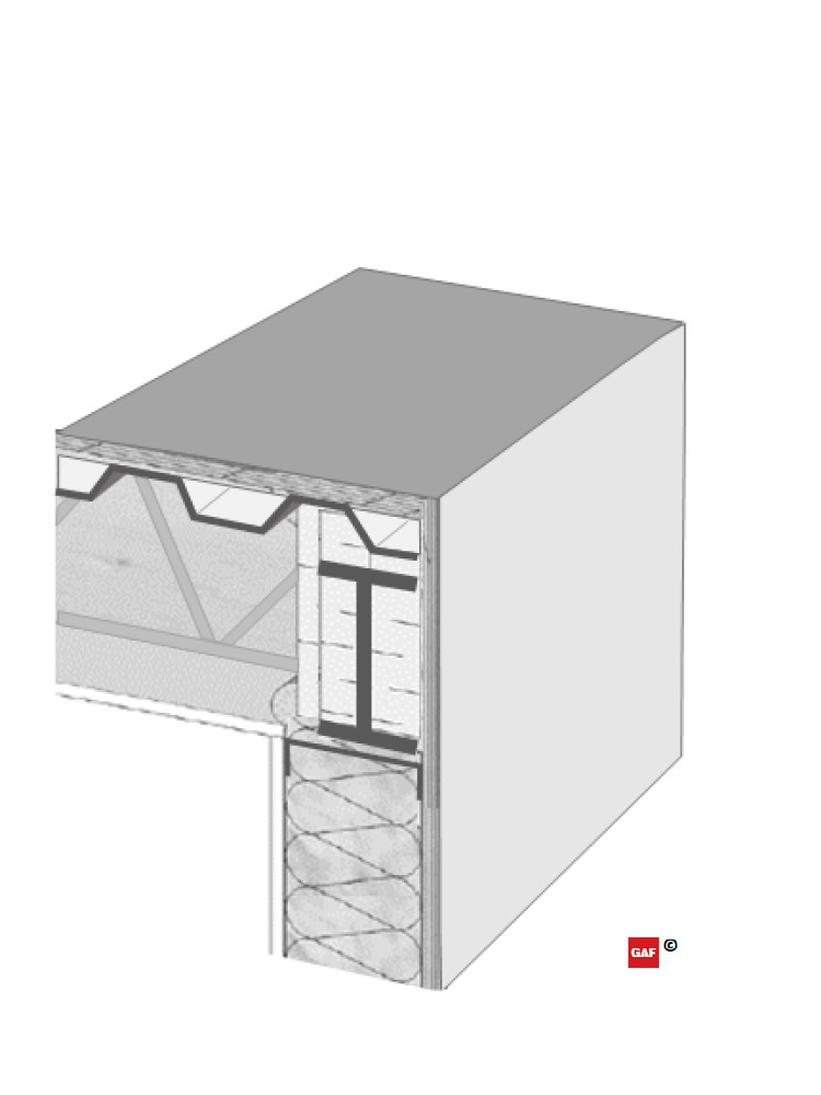
(Figure A) Initial condition.
a. In the initial condition, the wall and roof deck are assembled up to their sheathing. The roof structure is a corrugated steel deck with a substrate board placed on top to provide a continuous surface for later air barrier adhesion. The exterior wall is steel framed with cavity insulation and exterior sheathing applied.
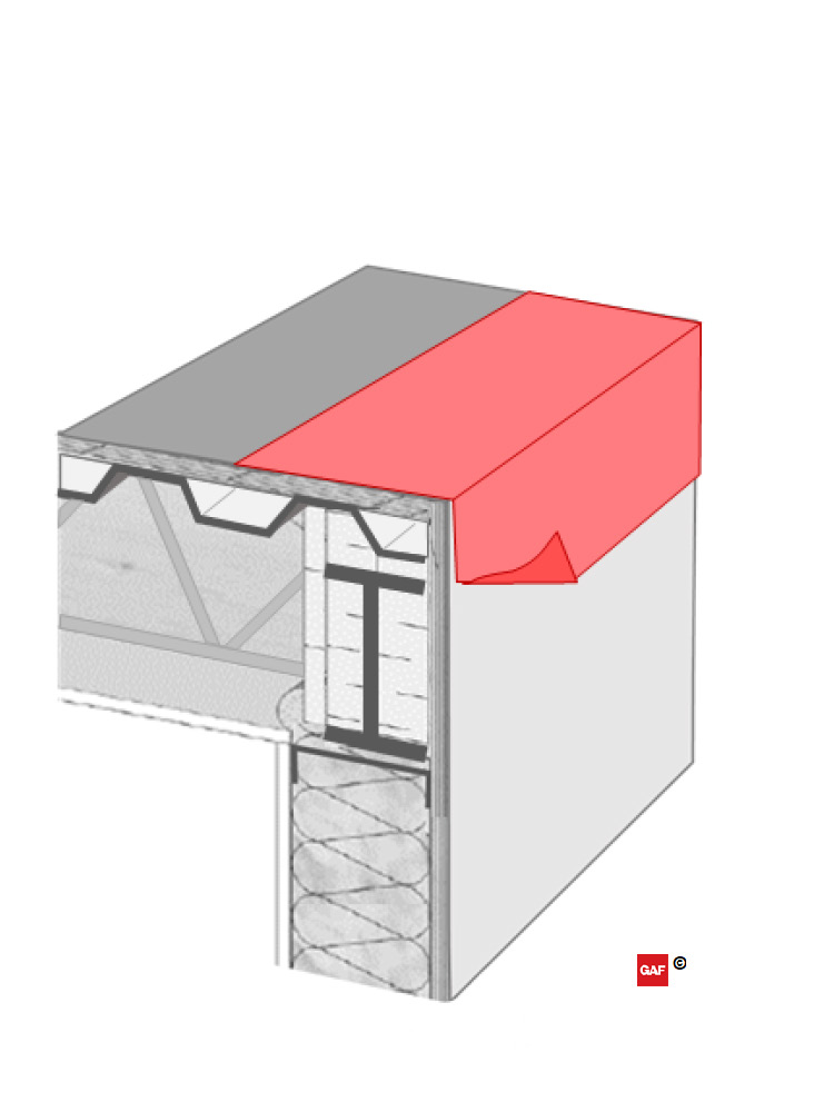
(Figure B) Pre-treated corner.
b. In preparation for the parapet wall construction, a strip of air barrier material is applied to the roof and wall edge with sufficient material for future integration with the remainder of the continuous air barrier. It is important to note the material on the wall side is not yet adhered to allow for future lapping to manage water in “shingle fashion” as required by the IBC. This can be accomplished by leaving a portion of the release liner in place for adhered materials.
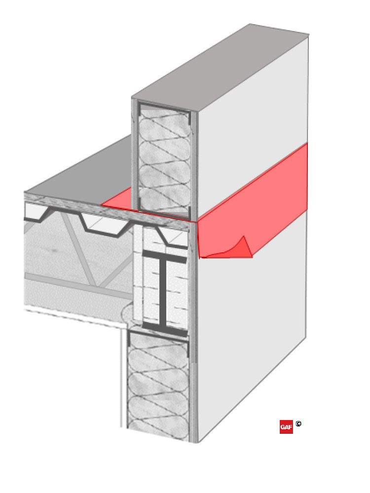
(Figure C) Parapet wall assembled.
c. The parapet wall is then assembled on top of the roof deck in a platform framed configuration. If lateral bracing for the parapet is required, additional detailing and coordination would be needed.
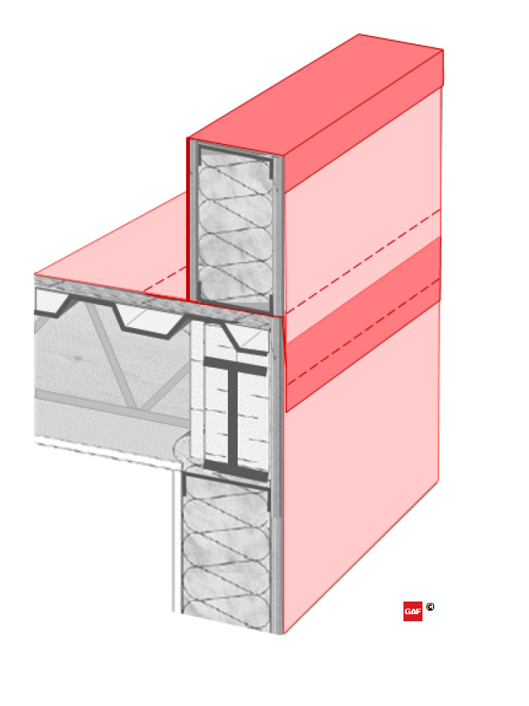
(Figure D) Air barrier integrated.
d. After the parapet wall is in place, the remainder of the continuous air barrier can be applied to both the roof and wall systems. It is notable that if the air control layer is also intended to act as the WRB in the wall and parapet system (as shown in Figure D), the application should start from the lowest point and work upward; this allows the subsequent layers to be lapped in shingle fashion. After the air barrier is applied to the walls (light red), the pre-applied strip of material can be lapped and secured over it (dark red in the center of the wall). The air barrier can then be applied to the roof deck (light red), up the backside and over the top of the parapet wall, and then terminate downward on the outside of the wall, lapping over in shingle fashion (dark red at the top of the wall). Lapped edges hidden behind the layers of air barrier materials are shown with dashed lines.
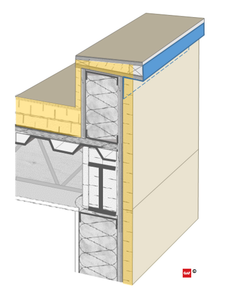
(Figure E) Continuous insulation installed.
e. The roof insulation and high-density coverboard can now be installed to the roof deck. These could be mechanically-fastened or adhered roof systems, but the use of mechanical fasteners through the entire roof insulation can have a significant effect on the thermal performance of the building.7 Continuous insulation is also applied to the backside of the parapet wall to maintain continuity. The parapet blocking for the coping cap can now be installed. In this case, it also includes a layer of tapered insulation to provide slope back to the roof area and extend the continuous insulation to the top side of the parapet. Wood blocking is included as required to accomplish fastening to meet ANSI/SPRI ES-1 uplift requirements. After the parapet blocking is in place, a piece of counter flashing (shown in blue) is required to lap over the WRB prior to the installation of the walls continuous exterior insulation; flashing will later lap over the coping cap, but without this piece pre-installed, there would be a discontinuity in the water control layer. The bottom edge of the flashing, under the wall exterior insulation, is shown as a dashed line.
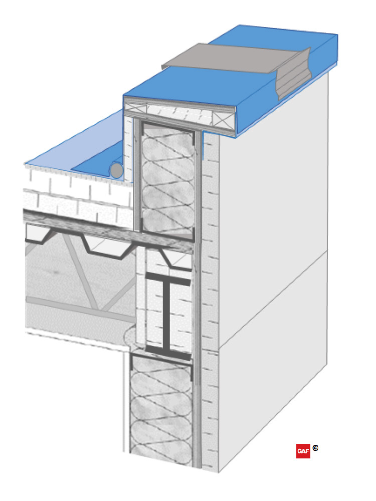
(Figure F) Roofing and terminations installed.
f. The roof membrane is applied to the roof area. An expansion joint may also be added at the joint between the roof and the parapet wall to allow for any expected movement between the systems. The membrane is then lapped and seams completed at the horizontal roof edge, extended up the backside of the parapet wall and terminated over the previously installed counter flashing on the face of the coping blocking. Terminating and lapping downward on the outside of the parapet wall maintains the continuity of the water control layer and provides a shingle-lap onto the secondary water control layer on the wall. The membrane over the coping blocking will also act as a secondary protection below the future coping cap. The coping cap attachment cleats and spline flashing are installed to the top edge of the parapet wall, bedding and treating the fasteners in sealant where they penetrate the membrane.
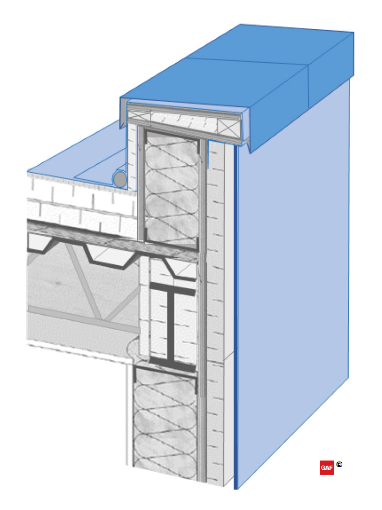
(Figure G) Coping and cladding installed.
g. The exterior cladding is then installed to the outside of the parapet and exterior walls (light blue). The coping cap is installed at the top of the wall, over the cleats and blocking (dark blue). The coping cap should be attached with the cleats as tested for by ASNI/SPRI ES-1, lapped over the cladding with drip edges on both sides, and maintain an overall slope towards the roof system to shed water.
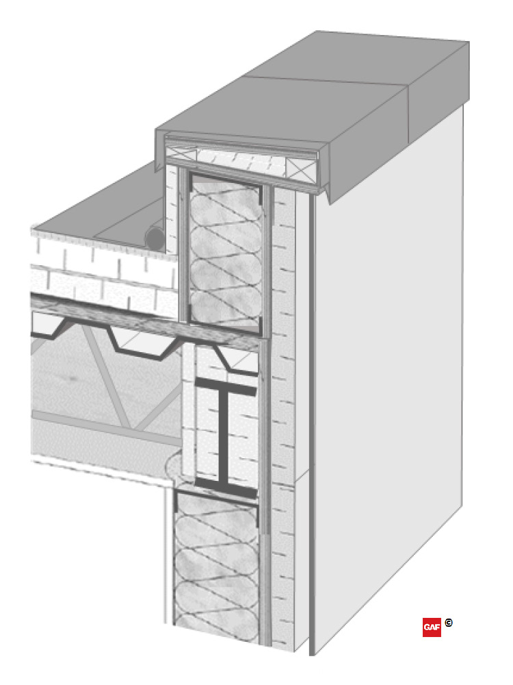
(Figure H) Final parapet assembly.
h. The parapet assembly is now complete. During the service life of the building, regular inspections and maintenance are needed to retain the performance of the parapet. Recovering or replacement of the roof system in the future should utilize as-built documentation to understand how to continue to manage the wall and roof system control layers.
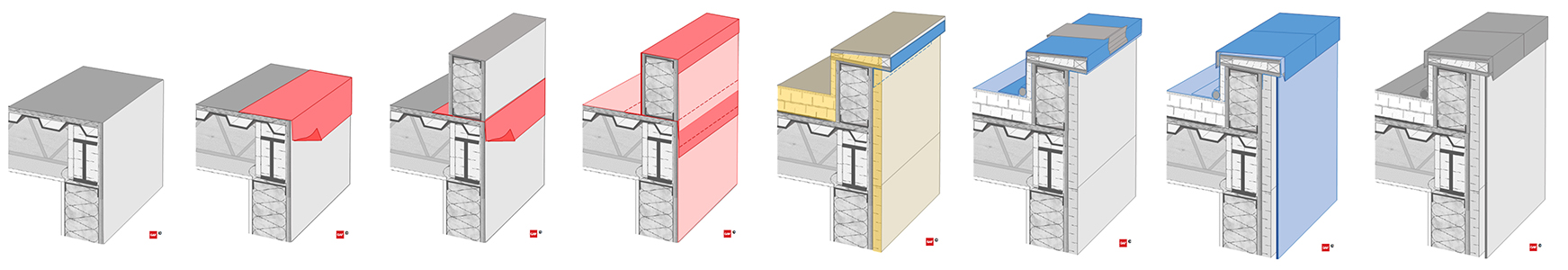
(Figures A-H; left to right)
