Designing for Fire Protection
Expanding the possibilities of wood design
![]() Continuing Education
Continuing Education
Use the following learning objectives to focus your study while reading this month’s Continuing Education article.
Learning Objectives - After reading this article, you will be able to:
- Analyze fire protection in wood buildings in terms of compliance with the 2018 International Building Code (IBC).
- Discuss the fundamentals of passive and active fire protection.
- Determine allowable wood use in buildings in accordance with the 2018 IBC.
- Describe provisions in the IBC for increasing the height and area of wood buildings beyond the base tabular amounts.
- Identify and select tested fire-rated wood-frame assemblies or, to use non-listed assemblies, calculate the fire endurance of load bearing and non-load bearing wood assemblies using the Component Additive Method (CAM).
Based on the Code Conforming Wood Design Series by the American Wood Council and the International Code Council.
Wood construction offers economic, performance and environmental advantages not typically found with other structural materials. Wood is cost effective, versatile and adaptable. It’s renewable and has a light carbon footprint. It also has a proven record for safety, evidenced by its use not only in 90 percent of all U.S. home construction but in some of today’s most innovative non-residential architecture.
In terms of fire protection, building codes require all buildings to perform to the same level of safety regardless of materials. Wood buildings can be designed to meet rigorous standards for performance, which is why the International Building Code (IBC) allows the use of wood in a wide range of building types—including structures that are taller and have more area than some designers realize.
This CEU provides an overview of fire protection in wood buildings with a focus on compliance with the 2018 IBC, and is based on the Code Conforming Wood Design Series developed by the American Wood Council (AWC) and the International Code Council.
Building fire safety incorporates a combination of passive and active features. A passive fire safety feature may limit the height and area of the building, prescribe the use of fire-resistance building elements or provide for adequate means of egress. Active fire safety features are those such as automatic fire detection or suppression systems that provide occupant notification, alarm transmittance and the ability to suppress fire growth until the fire service arrives. Codes are relying increasingly on active systems, since, with proper maintenance and alarm supervision, they have a high degree of reliability. This CEU covers the fundamentals of passive and active fire protection. It includes a summary of allowable wood use in buildings in accordance with the 2018 IBC, emphasizing the design flexibilities permitted for wood in non-residential and multifamily construction.
Passive Fire Protection
While most people are familiar with the basics of an active fire suppression system, including the use of sprinklers, fire extinguishers, etc., passive fire protection is what actually resists a fire at its point of origin. Passive fire protection, despite its name, is always at work. Components and systems are intended to contain fires or slow the spread of fires through the use of fire-resistant building elements such as fire-resistant floors and walls, and open space.
Occupancy classification or use of a building plays a key role in the organization and prescription of appropriate fire protection measures. Throughout the IBC, occupancy group classifications are fundamental in determining the necessary features of construction and occupant safety, including limitations to building geometry, means of egress, fire protection and interior finishes. For example, regulation of the size of structures is based on specific hazards associated with the occupancy as well as the characteristics of construction materials used.
The allowable area of a building is now determined in accordance with the applicable provisions of Sections 506.2 and 506.3. These sections yield area values that are determined in large part by the presence of passive and active fire protection systems.

Architect: CUBE 3 Studio. Structural engineer: Veitas & Veitas Engineers. Photo: CUBE 3 Studio & Rixon Photography.
Vox on Two in Cambridge, Massachusetts, includes four stories of wood-frame construction over a concrete podium.
Structural Frame
Although the combustibility of building materials is important in determining levels of safety, the expected response that a building will have in a fire condition is vital to determining equivalent risk, which is fundamental to the IBC. The code classifies structures by type of construction in an effort to account for the expected response that building elements will have in a fire. The IBC defines five main types of construction: Types I, II, III, IV and V. For each, it specifies the materials permitted and minimum fire-resistance ratings associated with the various structural members.
▶ Types I and II construction must only have noncombustible building elements, except as permitted in Section 603.
▶ Type III construction must have noncombustible or fire-retardant-treated wood (FRTW) exterior walls, while combustible or noncombustible materials may be used for interior elements.
▶ Type IV, often called Heavy Timber (HT)construction, has exterior walls made of noncombustible materials, cross laminated timber (CLT) or FRTW, and interior building elements made of solid or laminated timber without concealed spaces.
▶ Type V construction allows the use of both noncombustible and combustible materials in structural elements and in interior elements and exterior walls.
In the 2018 IBC, Types I, II, III and V construction are further subdivided into two categories (IA and IB, IIA and IIB, IIIA and IIIB, and VA and VB) with the difference being the degree of fire resistance required for various building elements and assemblies. For example, in Type VA construction, all interior and exterior load-bearing walls, floors, roofs and structural members are required to have a minimum 1-hour fire-resistance rating. In Type VB construction, no fire-resistance rating is required.
Establishing Fire Resistance
Table 601 of the IBC shows the required fire resistance of building elements (structural frame, walls, floors and roofs) for each construction type. Ratings are given in hours. The exception is Type IV, where the wood structural elements are assumed to have inherent fire resistance due to their required minimum dimensions (no fire resistance rating is necessary except for exterior walls). Required fire resistance is based on the expected intensity of a fire that originates within the building as a result of its fire load and the level of risk associated with the size of the building and its occupancy.
Fire resistance describes the rate at which a building material or assembly degrades due to a fire. Resistance is based on how rapidly the strength of the member or assembly is affected by the fire and whether the member or assembly can maintain its design strength while preventing the passage of heat or flames. Fire resistance of wood members and assemblies may be established by testing in accordance with Section 703.2 or any one of six means listed in IBC Section 703.3, which are based on the fire exposure and acceptance criteria specified in ASTM E119, Standard Test Methods for Fire Tests of Building Construction Materials or UL 263, Standards for Fire Tests of Building Construction and Materials. The most common methods—tested assemblies and calculated fire resistance—are discussed in the following pages.

Architect: Lord Aeck Sargent. Photo: Richard Lubrant.
At Crescent Terminus in Atlanta, stairs are designed with double stud walls providing a 2-hour fire separation. The team specified concrete block construction at the elevator shafts, and used a wood-frame wall to separate the elevator shaft from the rest of the construction. They also filled the interstitial space between floors with blown insulation instead of using sprinklers, which avoided technical concerns related to having sprinklers in inaccessible spaces.
Courtesy: American Wood Council
Tested Assemblies
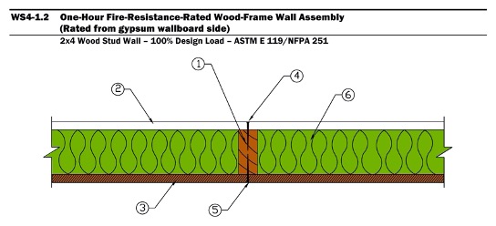
Code recognition of 1- and 2-hour wood-frame walls, floors, ceilings and roofs are predicated on successful fire and hose stream testing conducted in accordance with ASTM E119, Standard Test Methods for Fire Tests of Building Construction Materials or UL 263, Standard for Fire Tests of Building Construction and Materials.
Depending on the application, building elements may need to be fire-resistance rated from one side or both sides. For specific exterior wall applications where there is adequate fire distance separation from adjacent structures or the property line, the IBC allows exterior walls to be tested for exposure to fire from the inside only. Rating for both interior and exterior fire exposure is only required when the wall has a fire separation distance of less than 10 feet or less. For floors, ceilings and roofs, resistance to fire exposure is measured from below.
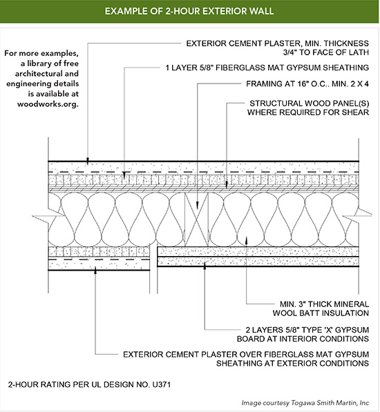
For a detail of a 2-hour exterior wall assembly, see page 8.
Calculated Fire Resistance
The fire resistance of exposed wood members may be calculated using the provisions of Chapter 16 of the National Design Specification® (NDS®) for Wood Construction (see IBC Section 722). AWC’s Technical Report No. 10 (TR10), Calculating the Fire Resistance of Exposed Wood Members and Assemblies, contains full details of the NDS method as well as design examples. Previous versions of the IBC contained a separate method of calculating fire resistance of exposed wood members, which was limited to 1-hour fire resistance. This provision was deleted in the 2015 edition of the IBC, since the NDS Chapter 16 method has broader application and provides a more reliable calculation procedure. The NDS, which is referenced in the IBC, also contains a calculation method for determining fire-resistance ratings for cross-laminated timber building elements.

Architect: CUBE 3 Studio. Structural engineer: Veitas & Veitas Engineers. Photo: CUBE 3 Studio & Rixon Photography.
Vox on Two in Cambridge, Massachusetts, includes four stories of Type VA wood-frame construction over a Type IA concrete podium. A 3-hour fire-rated horizontal assembly separates the wood-frame residential portion from the concrete garage. Fire walls were also used to divide the wood-frame portion of the structure into four separate buildings for the purpose of determining allowable height and area. (See Fire Walls on page 5.) A project of Criterion Development Partners, the 335,500-square-foot structure was completed in 2014 for a construction cost of $46.6 million.
CHAR

Photo: FPInnovations
Wood products such as the large beams used in heavy timber construction and cross laminated timber may perform better in a fire situation than noncombustible materials. Because these products are thick and solid, they char on the outside at a slow and predictable rate while retaining strength, slowing combustion and allowing time to evacuate the building. The char protects the wood from further degradation, helping to maintain the building’s structural integrity and reducing its fuel contribution to the fire, which in turn lessens the fire’s heat and flame propagation. Section 2304.11 of the 2018 IBC has prescriptive provisions for wood members which meet the definition of heavy timber.
Design Tools for Assemblies
Many sources are available for identification and selection of tested fire-resistance rated assemblies, including testing laboratories, evaluation reports, manufacturer's technical literature and industry publications. Fire-resistance rated wood-frame assemblies can be found in listings contained in such publications as:
▶ American Wood Council Design for Code Acceptance (DCA) 3 - Fire Resistance-Rated Wood-Frame Wall and Floor/Ceiling Assemblies
▶ Underwriters Laboratories (UL) Fire Resistance Directory
▶ Intertek Testing Services’ Directory of Listed Products
▶ Gypsum Association’s Fire Resistance Design Manual
Fire-resistance rated assemblies may also be selected from one of the prescriptive assemblies provided in IBC Section 721 based on ASTM E 119 or UL 263 test results, or by calculating an assembly’s capacity using IBC Section 722. AWC DCA3 is also helpful in determining the fire-resistance rating of wood-frame wall and floor/ceiling/roof assemblies, and is available free at www.awc.org.
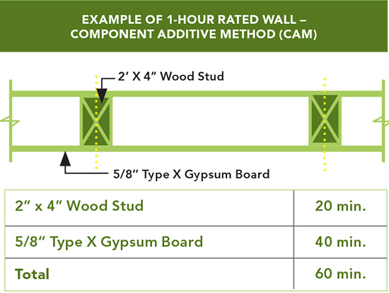
To permit use of “non-listed” assemblies, IBC Section 722.6 also recognizes a methodology for calculating the fire endurance of load-bearing and non-load-bearing wood assemblies (floor, wall, ceiling and roof assemblies) through a calculation methodology called Component Additive Method (CAM). CAM was developed in the early 1960s by the Fire Test Board of the National Research Council of Canada and validated through full-scale wood-framed assembly fire tests.
CAM calculates fire endurance to equal
the sum of:
▶
the contribution of the fire exposed membrane,
▶
the time to failure of the framing members, and, if applicable,
▶ additional protection due to the use of cavity insulation or reinforcement of the membrane.
Section 722.6 contains the procedures by which fire-resistance ratings of wood assemblies can be established using this calculation method. AWC’s publication DCA 4 – Component Additive Method (CAM) for Calculating and Demonstrating Assembly Fire Resistance provides a history of the method and an in-depth explanation of its use and application.
Courtesy: American Wood Council

Architect: Gensler. Structural Engineer: Martin/Martin. Photo: Matthew Millman.
For the Jackson Hole Airport in Wyoming, designers chose wood because of its varied grain and color palette, as well as its ability to perform structurally under a variety of loading conditions. The inherent fire performance of heavy timber construction was vital in allowing the wood to be exposed. Winner of a 2015 WoodWorks Wood Design Award.

Architect: EHDD. Structural engineer: Tipping Mar Structural. Photo: Jeremy Bittermann.
At the David & Lucile Packard Foundation company headquarters, wood was an important part of the strategy to achieve LEED Platinum certification.
Exterior Wood-Frame Walls
Wood stud framing is permitted for all load-bearing and non-load-bearing exterior walls in Type V construction. In Type III buildings, exterior walls may be fire-retardant-treated wood (FRTW) in compliance with IBC Section 2303.2 when the exterior wall assembly is required to have a 2-hour rating or less. In Type IV buildings, exterior walls may be of FRTW (the same as in a Type III building) or of cross laminated timber in accordance with Section 602.4.2. The required fire-resistance rating of load-bearing of exterior walls in Type III and IV buildings is 2 hours in accordance with Table 601. For non-load bearing exterior walls, the required fire-resistance rating is based on fire separation distance and occupancy group, in accordance with Table 602. In Types I and II construction, FRTW is permitted to be used in nonbearing exterior walls where fire resistance-rated construction is not required. FRTW can be used to bracing weather resistant cladding systems or to attach window and door units to the elements of the structural frame.
Interior Wood-Frame Walls and Partitions
In Types I and II construction, interior partitions dividing single tenant offices or retail and not creating corridors serving 30 or more occupants are permitted to be FRTW, 1-hour fire-resistance-rated construction, or wood panels or similar light construction up to 6 feet in height. In Types III and V construction, interior building elements may be wood. In Type IV construction, however, interior walls and partitions must be 1-hour fire-resistance-rated construction or solid wood construction formed by at least two layers of 1-inch matched boards or 4-inch-thick laminated construction (such as CLT).
Roofs and Rooftop Structures
In Type I and II construction, FRTW framing in roofs is permitted when certain conditions are met. FRTW framing can be used in roof elements in Type II construction of any height and in Type I construction of any height provided the vertical distance between the roof and floor below is at least 20 feet. Heavy timber is allowed in any construction type except Type 1A, where a 1-hour or less fire-resistance rating is required.
Separations and Openings
Exterior openings are generally required to be protected with a rated opening protective assembly when the exterior wall is within relatively close proximity (< 30 feet) of the property line. IBC Tables 601 and 602 determine when the exterior walls are required to be rated and Table 705.8 defines the allowable percentages of protected and unprotected openings in those walls.
Unlimited amounts of unprotected openings are permitted by Table 705.8 provided the exterior walls are 30 feet or more from the property line, or 10 feet or more in a Type IIB or VB building. No unprotected openings are permitted in the exterior wall within 5 feet of the property line for nonsprinklered buildings and no openings are permitted if the wall is closer than 3 feet from the property line.
Bay and oriel windows must conform to the type of construction required for the building; however, FRTW is permitted for Type I, II, III and IV buildings not more than three stories above grade plane. Untreated wood may be used in Type V buildings (IBC Section 705.2.4).
Interior wood doors are required to be protected when the wall assembly they are in requires a fire-resistance rating, such as interior exit stairways or fire partitions serving as corridor walls. The minimum required fire door assembly rating is given in IBC Table 716.1(2) and ranges from 20 minutes to 3 hours based on the type of assembly in which it is installed and the required fire-resistance rating of the wall assembly.

Cross Laminated Timber
A successful ASTM E119 fire-resistance test of a cross laminated timber wall was key to the decision to recognize CLT in the 2015 edition of the IBC. The wall, a 5-ply CLT specimen approximately 7 inches thick, was covered on each side with a single layer of 5/8-inch Type X gypsum wallboard. The wall was loaded to the maximum attainable by the test equipment, although it remained significantly below the full design strength of the CLT. It was then exposed to a standard fire that reached over 1,800 degrees Fahrenheit in the first 90 minutes of exposure. While only seeking a 2-hour rating as required by building code provisions, the test specimen lasted 3 hours 6 minutes.
Fire Walls
Ideally, fire growth and fire spread will be contained to the building of origin and any adjacent buildings will be protected against fire exposure. A fire wall, as defined in the IBC, is commonly used to divide a structure into separate buildings or to separate a new addition from the existing portion of a structure. Each portion of a building separated by one fire wall or more is considered a separate structure. Generally, fire walls must be of approved noncombustible materials, but may be wood-frame in Type V construction.
By definition: “A fire wall is a fire-resistance-rated wall having protected openings, which restricts the spread of fire and extends continuously from the foundation to or through the roof, with sufficient structural stability under fire conditions to allow collapse of construction on either side without collapse of the wall.” A fire wall is not required to be cantilevered and remain in place if construction on both sides of it collapses. Fire walls must extend to the outer edge of horizontal projecting elements, such as balconies and roof overhangs.
Chapter 7 identifies acceptable techniques and methods by which construction can be evaluated to determine fire performance requirements, including fire walls. In addition, NFPA 221: Standard for High Challenge Fire Walls, Fire Walls, and Fire Barrier Walls specifies requirements for the design and construction of high challenge fire walls, fire walls and fire barrier walls including protection of openings and penetrations. Fire walls are required to be designed and constructed to allow collapse of the structure on either side without collapse of the wall itself. When NFPA 221 is used in the design of a fire wall, it is deemed to have met the structural stability requirement specified in Section 706.2.
Exterior Wall Finish
Wood veneer is permitted on Type I, II, III or IV buildings up to 40 feet above grade—60 feet if FRTW is used, provided the veneer is 1-inch nominal thickness, 7/16-inch exterior hardboard siding or 3/8-inch exterior-type wood structural panels or particleboard. Open or spaced veneers without concealed spaces are not permitted to project more than 24 inches from the building wall (IBC Section 1404.5).
Interior Finish
IBC Table 803.13 places minimum finish performance classifications on finish materials based on their location within the building. They are expressed in terms of flame spread index numbers. These values are determined in a standard fire test which evaluates the surface burning characteristics of a material.
Different maximum flame spread indices are permitted depending on building occupancy, location of the material in the building, and the presence of sprinklers—Class A (flame spread index 0-25); Class B (26-75); or Class C (76-200).
The American Wood Council Design for Code Acceptance (DCA) 1 Flame Spread Performance of Wood Products Used for Interior Finish (https://www.awc.org/codes-standards/publications/dca1) provides flame spread ratings for many commonly used wood products.
The standard fire test used to evaluate flame spread characteristics of wood building materials is ASTM E-84, Standard Test Method for Surface Burning Characteristics of Building Materials. Nonsprinklered buildings typically require materials with lower flame-spread ratings than sprinklered buildings.
Tested wood products typically have a flame spread index of less than 200, making them acceptable under the IBC for a wide range of interior finish uses. Most wood species qualify as Class C, while some, such as cedar, western hemlock, Idaho white pine, redwood and spruce, can qualify as Class B.
Flame spread indices for a range of proprietary wood-based interior finish materials are available from manufacturers. Commercially available fire- retardant treatments for wood and panel products can reduce flame spread performance to an index of 25 or less, meeting Class A requirements.
Traditional wood floor coverings are exempt from floor finish requirements. Wood interior trim, such as baseboards, chair rails and handrails, are required to meet a Class C classification and cannot exceed 10% of the wall or ceiling area to which it is attached.
New Height and Area Provisions
Chapter 5 was revised in the 2015 edition of the IBC. However, the revisions focused primarily on format, to include increases for sprinklers into new tables with values and factors referenced in new height and area formulas. Though the equations and tables differed from the 2012 IBC, the resulting building sizes did not. This new approach has remained relatively unchanged in the 2018 IBC.
Open Perimeter Fire Protection
In general, there are two passive measures that decrease a building’s fire hazard: isolating the building from other structures and constructing the building with fire-resistive elements. IBC Chapter 5 provides for increases to the allowable area factor in Table 506.2 for the addition of open perimeter spacing, the use of noncombustible materials, and the use of fire-resistive elements and assemblies.
Isolating a building from adjacent structures decreases the fire hazard of a building as well as that of adjacent structures. The allowable area of a building is determined in accordance with the applicable provisions of Sections 506.2.1 through 506.2.4 and Section 506.3. In a single occupancy building with no more than one story above grade plane, allowable area is determined in accordance with Equation 5-1.
Equation 5-1:
Aa = At + (NS x If)
where: Aa = Allowable area (square feet)
At = Tabular allowable area factor (NS, S1, S13R, or S13D value, as applicable) in accordance with Table 506.2
NS = Tabular allowable area factor in accordance with Table 506.2 for nonsprinklered building (regardless of whether or not the building is sprinklered)
The area factor increase based on frontage (open perimeter) is determined in accordance with the following Equation 5-5:
If = [F/P – 0.25]W/30.
where: If = Area factor increase due to frontage
F = Building perimeter that fronts on a public way or open space having minimum distance of 20 feet (6096 mm).
P = Perimeter of entire building (feet).
W = Width of public way or open space (feet) in accordance with Section 506.32
Allowable Increases for Frontage Distance
Buildings located next to a public way or open space adjoining a public way, with the exterior wall a minimum width of 20 feet from the public way for more than 25% of the building perimeter, may qualify for an area factor increase based on frontage distance in accordance with Equations 5-4 and 5-5.
Equation 5-4:
W = (L1 × w1 + L2 × w2 + L3 × w3…)/F (Equation 5-4) where:
W (Width: weighted average) = Calculated width of public way or open space (feet).
Ln = Length of a portion of the exterior perimeter wall.
wn = Width (≥ 20 feet) of a public way or open space
associated with that portion of the exterior perimeter wall.
F = Building perimeter that fronts on a public way or open space having a width of 20 feet (6,096 mm) or more.
Equation 5-5:
The area factor increase based on frontage is determined in accordance with the following
If = [F/P - 0.25] W/30 where:
If = Area factor increase due to frontage
F = Building perimeter that fronts on a public way or open space having minimum distance of 20 feet (6,096 mm)
P = Perimeter of entire building (feet)
W = Width of public way or open space (feet) in accordance with Section 506.3.2
It should be noted that frontage widths (W) greater than 30 feet will only receive credit for a value of 30 feet. The maximum increase that can be obtained for frontage would occur when 100% of the perimeter has frontage of 30 feet or more and would result in an area factor increase of 0.75.

Active Fire Protection
Active fire protection is characterized by detection and response. Detection of a fire through smoke or heat sensors initiates a chain of events that reduces threats from the fire. Once a detection system is activated, other programmed actions ensue, including: sounding of alarms, closure of smoke and fire dampers, closure of automated fire doors through de-energizing of magnetic door stops, and opening of fire sprinklers or other fire suppression system. Once detected, the fire can be controlled or extinguished manually through the use of extinguishers and fire hoses or automatically by fire sprinklers, fire fighting foam systems, hypoxic air systems or other devices.
IBC Chapter 9, Fire Protection Systems, prescribes minimum requirements for active fire protection systems to perform one or more of the following functions: detect a fire, alert the occupants or fire department of a fire emergency, control smoke, and control or extinguish the fire. Fire protective systems must be installed, operated and repaired in accordance with the International Fire Code (IFC).
Automated Sprinkler Systems
Automatic sprinkler systems must be equipped with approved audible alarms that are monitored for integrity by an approved supervising station. The alarm must be installed on the exterior of the building in a location approved by the building official. This alarm is not intended to be an evacuation alarm. However, when a fire alarm system is installed, the sprinkler system must be interconnected with the building fire alarm system so that, when the sprinkler system activates, it sounds the evacuation alarms required for the fire alarm system.
Where the code requires that a building or portion thereof be equipped throughout with an automatic sprinkler system, the sprinklers must be in accordance with NFPA 13, Standard for the Installation of Sprinkler Systems. However, where allowed in buildings of Group R occupancy, up to and including four stories and not greater than 60 feet in height, the automatic sprinkler system may be in accordance with NFPA 13R, Standard for the Installation of Sprinkler Systems in Low-Rise Residential Occupancies.
IBC Chapter 9 regulates the installation of automatic sprinklers in a building based on certain factors, such as occupancy group, height, size of the building/fire area, and occupant load. All water supply control valves and water-flow switches are required to be electrically supervised in accordance with Section 903.4. Central stations, remote supervising stations or proprietary supervising stations are approved services recognized in NFPA 72.
Note: The construction of one- and two-family dwellings is generally governed by the provisions of the International Residential Code (IRC), which allows the installation of an automatic sprinkler system in accordance with NFPA 13D, Standard for the Installation of Sprinkler Systems in One- and Two-Family Dwellings and Manufactured Homes. If the one- or two-family dwelling does not comply with the building geometry limitations of the IRC, then the building must comply with the requirements of the IBC and an NFPA 13D system can still be used, but the installation of the 13D system will not provide for any increases to the allowable height or area. Automatic 13D systems in one- and two-family dwellings do not require electrical supervision, through exception.
Sprinklers offer a substantial increase to life safety, which is well documented and merits the consideration of designers for that reason alone. But their advantages can also be economic. The code offers considerable trade-offs for providing sprinklers, including:
▶ Increases to allowable heights and areas
▶ Reductions in corridor ratings and corridor opening protection
▶ Flexibility in means of egress (travel distance to exits, number and separation of exits, common path of travel)
▶ Reductions in dwelling unit separations
▶ Relief from emergency escape openings
▶ Relief from certain fire and smoke damper requirements
▶ Interior finish flexibility
Allowable Increases for Automatic Sprinkler System Protection
Under previous versions of the IBC, an allowable increase of either 200% for a multi-story building or 300% for a one-story building was permitted. However, the 2015 IBC introduced a new, more user-friendly method of determining allowable increases which has been retained in the 2018 code. Maximum allowable height and number of stories can now be determined directly from Tables 504.3 and 504.4, and the maximum allowable sprinkler area increase can be determined from Table 506.2. These tables now have factors for both nonsprinklered buildings, and sprinklered buildings with NFPA 13-, 13R-, and 13D-compliant systems, which are tabulated for both single story and multi-story buildings.
Chapter 9 Area Limits for Nonsprinklered Buildings
Many occupancies have area thresholds beyond which sprinklers are required per IBC Section 903. The same thresholds apply to all construction types. When increases are taken for open frontage in nonsprinklered buildings, the allowable area per floor can exceed allowable fire areas and a sprinkler system may be required. If sprinklers are provided, however, allowable area increases for both sprinklers and open frontage may be taken. Alternatively, fire areas may be kept below sprinkler thresholds by compartmentalizing floor areas with fire-resistance-rated construction in accordance with the definition for fire area and the requirements of Chapter 7.
The requirement for sprinklers can also be triggered by specific use, height above grade, or occupant load. For instance, although unsprinklered Group A-2 occupancies (restaurants) may exceed one story above grade in Type III construction, if the A-2 is above the level of exit discharge (typically the first story), or has an occupant load exceeding of 100 or more, the A-2 building must be sprinklered in accordance with IBC Section 903.2.1.2. Increases for both open frontage and sprinklers could then be taken.
Unlimited Area Buildings
Section 507 provides provisions which allow buildings to be of unlimited area. As an example, the area of a nonsprinklered one-story F-2 or S-2 building is not limited provided the building is surrounded and adjoined by public ways or yards not less than 60 feet in width. This particular provision applies to any construction type.
Safeguards during construction
IBC Chapter 33 provides minimum safety precautions for fire during construction and the protection of adjacent public and private properties. The section includes provisions for fire extinguishers, standpipes, means of egress, and sprinkler system commissioning. The IFC also contains detailed requirements for fire precautions during construction.
Fire Extinguishers
During construction, one portable fire extinguisher shall be placed at each stairway
on all floor levels with combustible materials, in each storage or construction shed and where special hazards exist, such as the storage and use of flammable and combustible liquids.
Maintaining Means of Egress
Required means of egress must be maintained at all times during construction, demolition, remodeling or alterations and additions to buildings. During construction, when a building height exceeds 40 feet above the lowest level of fire department vehicle access, a minimum of one temporary
Standpipes
In buildings required to have standpipes, not less than one standpipe shall be available during construction for fire department use. The standpipe shall be installed before the construction is 40 feet above the lowest level of fire department vehicle access. The standpipe is placed adjacent to usable stairs and has fire department hose connections. The standpipe is extended during construction to within one floor of the highest point of construction having flooring per IBC Section 3311. During demolition a standpipe shall be maintained in operable condition. The standpipe may be demolished floor by floor as demolition proceeds, but not more than one floor below the floor being demolished.
Sprinkler System Commissioning
The sprinkler system must be tested and approved before the certificate of occupancy is awarded per IBC Section 3312 and the building is occupied, except as provided in Section 111.3, temporary occupancy.
Fire watch during construction
The 2018 IFC, which is directly referenced and made applicable by Section 3302.3 of the 2018 IBC, has comprehensive requirements for fire watches and fire prevention that are to be performed by the building owner or contractor. In addition, Section 3314 of the IBC requires a fire watch in nonworking hours when construction exceeds 40 feet above grade, if required by the fire official.
Additional Requirements
Additional requirements in the IFC include:
▶
Temporary heating equipment must be listed and labeled; installation and maintenance of the equipment must be in accordance with the listing (IFC 3303).
▶
Smoking is prohibited except in approved areas with posted signage (IFC 3304).
▶
A fire watch must be maintained with qualified personnel if required by the fire code official and records of fire watch activities must be kept and provided when requested (IFC 3304).
▶
Welding operations must follow the provisions of IFC Chapter 35. Electrical wiring must follow the provisions of NFPA 70 (IFC 3304).
▶
The owner must designate a fire prevention superintendent responsible for the fire prevention program during construction. Requirements for the program are listed in IFC Section 3308.
▶
An accessible emergency phone is provided in an approved location at the construction site. The construction site street address and fire department emergency phone number must be posted by the phone (IFC 3309).
▶
Fire-fighting vehicle access must be provided within 100 feet of temporary or permanent fire department connections (IFC 3310).
▶ An approved water supply for fire protection must be available when combustible material is at the construction site (IFC 3312).
▶ Requirements for safeguards during roofing operations are listed in IFC Section 3317.

Photo: VanDorpe Chou Associates
NEW WEBSITE: CONSTRUCTION
FIRE SAFETY
Although less than 2% of building fires occur during construction, this phase presents unique risk scenarios that make any building more vulnerable regardless of material. The IBC provides extensive safety precautions for this phase, but the fires that do occur are often caused when required elements—such as fire doors, smoke alarms and sprinklers—have not been put in place. For this reason, construction site fire safety includes some unique challenges that are best addressed through education and increased planning.
A new website, https://constructionfiresafety.org/, offers information and resources on construction fire safety from a broad range of sources. It identifies best management practices, places emphasis on personal accountability of stakeholders, and provides guidelines for using model codes and standards to reduce fire loss.
Summary
Wood construction offers advantages in terms of cost, design versatility and sustainability—while meeting code requirements for safety in buildings that range from schools and offices to mid-rise/ multifamily, civic, institutional, industrial and retail. Building codes focus on fire resistance and fire performance which improves occupant life safety, fire responder safety, exposure protection, and building integrity. Fire performance testing is giving way to regulating material combustibility. This provides building material manufacturers with a clear understanding of how products must perform in certain instances, while allowing designers greater flexibility in product selection. The 2021 IBC will contain new mass timber construction types, a first for model codes, which will allow wood structures to exceed the current height and area limits in the 2018 IBC. Wood has a history of proven structural and fire performance, and is making history with new mass timber products such as CLT, which offer exceptional strength and continue to expand the possibilities wood design. For more detailed information on the subjects covered in this CEU, a new version of the American Wood Council’s Code Conforming Wood Design based on the 2018 IBC is available as a free download at as a free download at www.awc.org.